I have a suggestion that I wanted to run by you for auto calibration of the camera.
I’m thinking that I should be able to put an 11" x 17" piece of paper into the bed of the machine.
That paper is cheap and easily accessible to everyone on the planet.
Then, run an auto-calibration program within your UI.
It would have 5 cross hairs. 1x in the center and 1x for each corner.
The auto-calibration would score or cut the cross hairs and then use the camera to see the results.
Based on the results relative to the intended cut, it would automatically calibrate the camera so that the next print would actually cut where it is supposed to according to the image.
Are you thinking this would be something a user could do periodically, or maybe just once, or maybe before each cut?
If it would be helpful to do periodically, I like it!
If it could be done just once, they could save us the trouble and just do it at the factory (which they already do, I believe). Unfortunately, if it was to be done before each cut, there would be issues with small objects. The paper would have to be held at the same height as the object, and if you were doing something you only had one of, say a cell phone, you’d then have to hold up the paper with some kind material that was the same thickness as the phone in order for the calibration to be useful. (the paper would just drape over small objects and end up lying on the surface of the bed)
I was thinking it might have to be done each time you turn the machine on.
You could even re-run it if you have the machine on for a long time and you just want to make sure it is going to be accurate for the next project.
I am hoping you could calibrate using the paper on the bed itself and the results would be sufficient regardless of the thickness of material you put in later (up to the thickness limit of course). Maybe that’s wishful thinking.
I don’t know enough about what is going on with their machine vision to know how good of an idea this is but I like the concept if it is doable.
I’d think a target like this would be delivered on a piece of their draftboard.
Draftboard isn’t cheap, but 11" x 17" paper is. Plus, you can buy it anywhere.
As long as you use the same weight of paper, I’d expect pretty similar results.
Don’t forget that it doesn’t even matter if you actually cut through the paper or not.
The point of the auto-calibration is to simply mark the paper and compare the intended mark to the actual.
I will attempt to do exactly that if they haven’t fixed the calibration by the time I receive mine. I will use a grid of cross hairs rather than just 5.
It should only need to be done once unless you move the machine unless the lid hinges are flaky.
Some of the dewarp is compensation for the lens and that should not vary for a particular lens although it will vary from lens to lens. The rest is for the camera position and orientation. Hopefully that doesn’t vary. If it does I would consider modifying the hinges / lid.
The reliance on the lid camera is a major design flaw. I felt it was a gimmick the first time I read about the GF, but I chose to order anyway, not realizing they were going to use it to do everything. An engineer with even a hint of “design for manufacturing” experience would have realized this was a mistake.
I’d like to see them move away from dependence on it. It should be a “nice to have” feature, not a critical component. The novelty of “gee, I can (roughly) capture an image I drew on the material and then cut it” wears off in a matter of minutes, and you just want to be able to reliably and consistently place objects, have accurate cuts, workable over-travel stops, etc.
A full solution might require new hardware. There should be an upgrade option for those stuck with the lid camera.
Well I am one of those but I have experience of pick and place machines that use computer vision to place object very precisely and also use computer vision for quality control. So when they advertised it as already doing this I believed them. I still don’t think it is impossible.
They have a diversity policy for recruitment but they seem low on grey beards!
But do those P&P machines use a single fish-eye lens to determine where to place the component on the PCB? A check for QC can be as simple as comparing an image of a known-good board with the device-under-test. That’s a lot different than using a single, fish-eye camera to try and place or align something with high precision.
Very true but the GF does have a head camera as well.
I would expect the lid camera to be able to allow alignment to about its pixel resolution even if that isn’t great at the corners. I would be happy if the finished part at least looked like it was in the right place when viewed from the camera. At the moment you can clearly see it is way off in the camera view, so the camera resolution isn’t the limiting factor, it is the de-warping algorithm. That should be easy to correct by engraving a grid, taking a shot, finding the crosses in the image and then warping the image so they appear in the correct place and interpolating in between.
The camera can also see outside the crumb tray. I don’t know why they didn’t put some fiducials in the corners of the machine to allow the lid alignment to be compensated for and have a fixed relationship with the axes so they don’t need to restrict the axis movement.
All good points. I suspect we’ll see a number of changes like this in version 2.
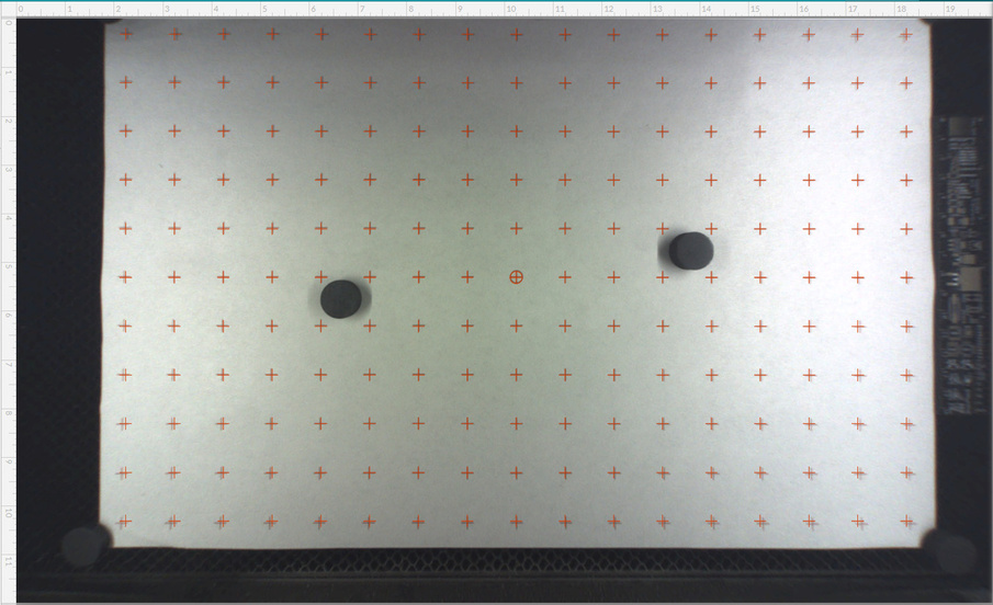
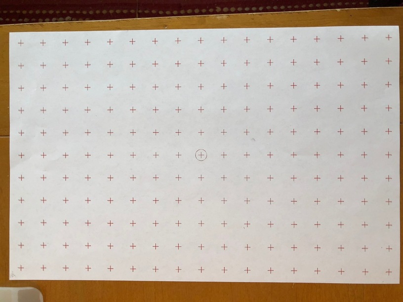
For those that are interested, I created an alignment grid on some 11x17 inch paper, and took some screen shots before and after a print. You can clearly see some uncorrected lens distortion as you move off the center. I’m not sure how GF is even able to correct for this without something in the machine to key off of. They should ship a laminated alignment card to customers, and then have a procedure to calibrate the camera correction off of that.
Picture showing post cut. Note, this is not the cur corresponding to the image above. This is a slightly different grid, and I manually adjusted the offset in the GFUI to make the center cut aligned with the center crosshair on the paper. The cut is pretty much spot on, except for a slight rotation that is probably due to how I placed the paper in the bed.
I think they grabbed some calibration data at the factory and plan to use that to fix the camera view. Quite likely it is just a photo of a grid like yours.
No, I believe they can recalibrate after that. I know this because when I first got my unit, the camera picture was WAY off. I contacted support, and Rita did something and it all got better.
But even if all that was based on a factory image, they should provide the customer with something that can be used to recalibrate correctly when needed - as the lid shifts a bit with use, for example.
Or just engrave your own on paper. The motion is always pretty accurate and there is not much point in having a more accurate grid than the motion is capable of.
I think you might have missed my point. All I’m saying is that you should be able to use regular paper that can be purchased anywhere and roughly is the same size as the Glowforge bed. If that’s A3 for you, awesome.
The concept is still the same.
I certainly understood your point. But tossing around the phrase “everyone on the planet” in this case is equivalent to saying “everyone on the planet” measures in feet and inches. Nope, it’s just us.