Posting in “Problems and Support” because I can’t post in Tips & Tricks yet (I think this would be a useful thing for other people?), but also I’d be keen to hear from Glowforge in regard to the questions at the bottom.
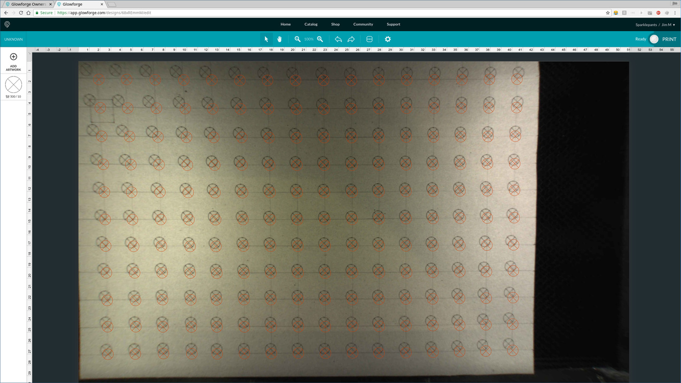
Anyway, I drew a 25mm grid on a sheet of card, and laid out cross markers in the GFUI according to the camera position, then did a shallow cut operation. (Yes laying out the markers was boring!). The result is that I now have a relatively good picture of how the calibration varies over the work area that I can reference.
I realise this isn’t quite good enough for accurately placing something on an existing piece (I can use a jig for that), but still it’s useful for other situations where the accuracy only needs to be ~1-2mm. (And now I know where the most accurate area is).
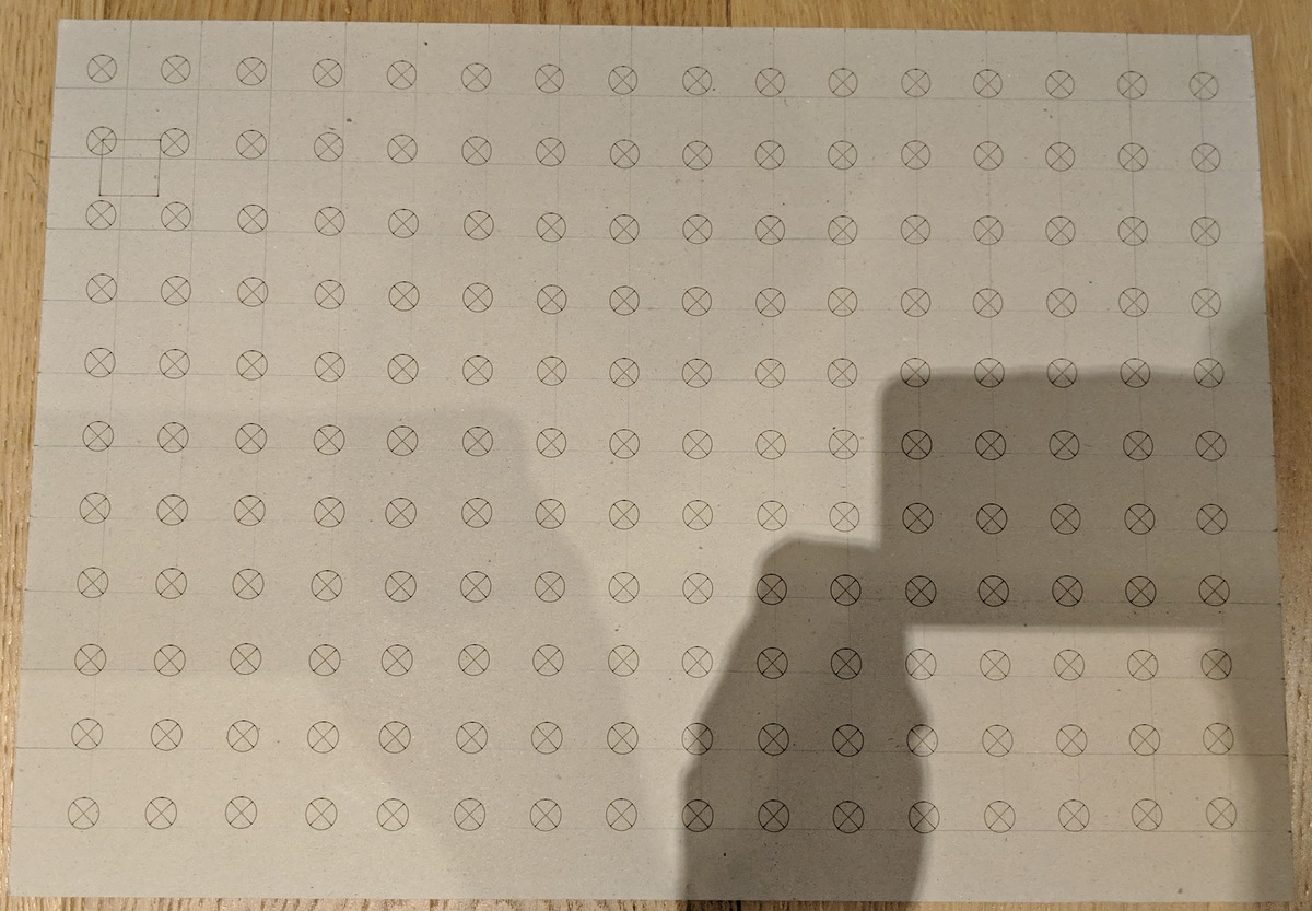
And here’s my handy reference card:
So:
Is this a “normal” amount of calibration error?
It would seem that the error is exactly the camera distortion. Like it’s a continuous function over the area, it would be straightforward enough to describe mathematically – if only I could apply that function to the calibration data that Glowforge has for my printer.
That’s true for the depth at which you scored, but I believe it’s a 3-dimensional function also varying as the depth changes… Another test?
That said, I haven’t seen a map this detailed before, that really took some patience! It’ll definitely help you with manual placement while we wait for improvements.
The thing I’ve been curious about but haven’t had the patience to try is: if you lie about the material height, can you get it to come into alignment? That is, by try gradually stepping up and down from the real height, is it possible to arrive at an offset that corrects for the camera miscalibration, or is it more complicated than that.
I think it’s more complicated than that. Or perhaps I misunderstood you. But my impression is that you would have to tell a different lie for every different thickness of material, and you might even have to lie differently depending on where you were placing things. My machine is only slight wrong directly under the camera, more wrong elsewhere, but not (afaict) in a completely linear fashion.
Not to mention that by telling it the wrong height it would mess up the laser focusing. Although I guess you could fudge the height, lay out everything, then set the height back before clicking “Print”. But if the only thing you’re fudging for is the lid-camera to crumb-tray then I could imagine this could conceivably work (I’m curious enough that I’ll test it tomorrow). One way to see would be whether straight lines in the stock become straight lines in the preview image.
The calibration error is not a linear transformation (because it’s a fisheye lens and camera distortion). But it can be still described mathematically and in theory you could extract the parameters for an approximation of the error function from a print like what I showed above. This isn’t enough to fully calibrate the lens from scratch, but it would be enough to improve it.
I’ve seen references on the forum to people who’ve had their calibration fixed “magically” by Glowforge by what sounds like them analysing the before/after bed images from the gift-of-good-measure print. Would love to know from Glowforge staff if this is true?
It’s a fisheye lens so the distortion is not linear, but what I’m curious about is whether over or under correcting would bring it into alignment.
It actually wouldn’t – the laser focus doesn’t use the value entered for material height. That’s only for camera correction. The laser auto-focuses using the red dot during the “scanning” step after you click print.
I should be clear, I’m not proposing this as a fix or a workaround, it’s merely an idle curiosity and something I’ve wanted to try as an experiment.
That would be interesting if true. I don’t think there’s enough resolution in the lid camera images to do something like that. We’ve been told that they have all kinds of ultra precise calibration data from the factory, and that in the future everyone’s machines would keep getting better as they improve the software’s ability to use that data. I have a personal speculation about what that means: I think they put a jig in the machine and take a bunch of pictures of targets with the lid camera and the head camera. Those are then used as input to train a machine learning algorithm, which is a computationally expensive task. This produces, for each individual machine, a set of model parameters that are used for things like lid camera dewarping. In principle, it’s possible to compensate for any slop in the manufacturing process with this procedure, but machine vision being what it is, the answers are only approximate and everyone’s model ends up slightly out of tune.
Continuing the wild speculation, I think the reason it gets better (or worse) occasionally is that they’re tuning the algorithms, and in particular they occasionally re-process the original calibration data for some or all machines. It’s almost guaranteed that a different answer will come out, so you find that one day instead of being shifted 0.18" to the left, it’s 0.06" to the right. They probably have the ability to manually trigger reprocessing for one machine, or do them all in a batch. Glowforge is confident that any problem can be solved through complicated software, and they might be right. I think we could get quicker results by placing a few fixed points on the bed and then asking a human to zoom in and click on them. That should be enough to characterize the lens. But it’s not as sexy as deep learning.
Yep I sure wish there was a way to calibrate the camera at home.
To answer your earlier question it sure seemed to be related to material height on my first machine. Calibration was nearly perfect until entering material height at which point if you tried to align a design with the camera all bets were off. I regret not having done more tests on it.
I’m not an official voice, but it looks to me like yours is off in the photo by almost a full cm in some spots, which would be more than the allowed 1/4". I suspect Support will want to see some tests on PG draftboard in order to make their determination.
I’ve done this before (just messing around) on aligning the overlay to the actual cut after it’s been cut and you can indeed make it match reality. Going off of memory, I did it on some puzzles - they are .09”, and IIRC going somewhere up to or around .230-250” brought it into alignment.
Whether that would work for every machine is a different question. It would mean you would need enough “adjustment” between your actual material height and your fudged height settings but still being within the allotted 0.00”-0.500” entry settings.
FWIW, I’ve never noticed that my post-cut image differs from my pre-cut image like some have reported. Both are the same for me.
Post-post thought: it might be interesting to make the cut, measure the actual offset (you can do this extremely accurately in Photoshop), and then apply that offset to the height entry and see what it actually gets you. Ex. My material height of .09”. Measure the offset (i don’t know mine exactly in the corners) but let’s say it is .200. Add the .200 to the .09” and see how close it gets you…
Interesting. That suggests that registration could be improved by showing a post-cut image and letting the user adjust a slider to bring the preview into alignment.
Same here. I think this is a case of expectations influencing perception.
Can you please do the following to help me evaluate your alignment error?
Turn off your Glowforge.
Check for small pieces of debris or dust.
Check the lower door to make sure it closes all the way. It may require some force to open, but open it, wipe any dust off the edges, and close it all the way.
Remove the tray and clean any dust or debris from the surface underneath. Pay careful attention to remove all debris from the four dimples where the tray rests.
Check the lid to make sure it closes all the way. Small particles of material, such as dust or debris, can prevent it from closing completely.
Check the surface your Glowforge is on to make sure it’s flat. Ensure it is not twisted slightly and that there is no debris propping up one side of the machine.
Turn your Glowforge back on.
We included an extra piece of Proofgrade Draftboard with your materials shipment for troubleshooting. Place the Proofgrade Draftboard in the center of the bed and print the Gift of Good Measure using the default settings.
When the print finishes, leave the lid closed and wait until the fans stop and the picture updates. Without moving your artwork or your material, take a screenshot of the Workspace to show us the difference between the artwork placement and the actual print placement. Make sure to include the rulers in your screenshot and show as much of the bed as possible.
Mac: Press Shift-Command-4 and click and drag a box around your image. You’ll find the screenshot file saved on your desktop.
Windows: Click on the Start Menu and type “snipping tool”. Open the Snipping Tool > New then click and drag a box around your image. Click the Save icon and name and save your file.
Send us the screenshot along with the date and time of the print, and we’ll investigate.
Perhaps - but I feel like the distortion is pretty complex. I haven’t looked at a raw bed image lately so can’t recall for sure. Complex would be a combination of barrel and pincushion (sometimes called wavy or mustache distortion). At minimum it’s a large amount of barrel distortion they are trying to correct. And depending on whatever factors, that distortion isn’t always equal between the different quadrants (ie Top Left not matching top right distortion, etc). I know on mine it’s different, largely because I have a skewed/trapezoidal view, from left to right.
It’s been a little while since I’ve seen any replies on this thread so I’m going to close it. If you still need help with this please either start a new thread or email support@glowforge.com.