This is what I came up with in Affinity Designer to replicate the design that @Jules did with @marmak3261 with Illustrator and Inkscape in this thread, and @smcgathyfay and @johnwills did with Corel here
<a class=“attachment”. href="//cdck-file-uploads-global.s3.dualstack.us-west-2.amazonaws.com/glowforge/original/2X/9/9e5317fa19540c418674d868d18dcad8815fd8e6.pdf">Celtic Knot in Affinity Designer.pdf (1.0 MB)
Edit: forgot the SVG file creation step. File|Export, choose SVG, adjust options if necessary, then choose a name and location.
I am thinking about how I would design this with OpenSCAD. It can export SVG files for 2D objects but as it only models solid objects it exports paths with a black stroke 0.5mm wide and a light grey fill. There is no control over the colour and you can’t have a stroke without a fill as that isn’t a 2D solid object.
I can import the SVG into InkScape and change the colours and fill, etc, but for the Celtic Knot I would need to export the outline and the engrave separately, remove the fill from the outlines, remove the stroke from the engrave and change the colours. Not too bad for a one off design but a but of a pain if it needs to iterate, or change parametrically.
I could write a Python script to automate this using specially named modules to represent the cuts and the engraves.
Since the end result is actually a 3D object it makes more sense to model it in 3D. It would basically be a ring with an embossed design and that would produce an STL file. I can write a program to turn it into a grey scale image. The ring would be white with the engrave in grey and a black surround and black centre where there is no material.
Obviously I would not want the Glowforge to engrave away the centre and all the surrounding material. I would just want those cut as outlines. Is or will the 3D engraving software be clever enough to cut around the black areas and let them fall out if the max engraving depth is set equal to the material thickness?
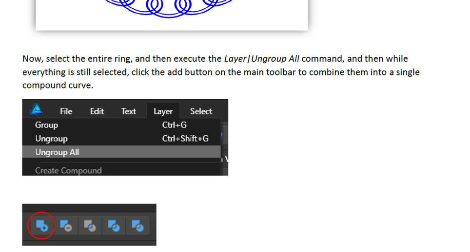
After some research on the subject, I was reminded that the Create Compound menu option would have by default had the same effect on the final outcome as my having used the Add button in this instance. The difference is that the Create Compound command is non-destructive, in that it nests all the selected objects inside a new “Compound” object in the layers panel, which allows you to then change the compound mode of individual objects within the Compound group, and even to add and remove objects at will. It looks like objects get the “Add” compound mode by default when using the menu option to create the compound. However, there is another way to create them too if that isn’t what you need; you can alt-click the Add, Subtract, Difference or Intersect button on the toolbar to create one with the mode you need.
For this specific case, the destructive (i.e. not reversible other than via undo) Add command was fine, but for more complex designs, I can see where the incredibly flexible create compound functionality would be very useful.