I think eflyguy is close with his suggestion of wave interference. I do not think it is the laser, I thing it is interference between drive step size and the LPI setting.
My suspicion/theory: Banding is a result of the wave interference pattern between the LPI requested for an engrave and the “natural” frequency of the drive which is driven by the size of the pulley and the resolution of the stepper motors. The forge’s smallest motion increment is finite. One could consider this the “native LPI” of the machine. Banding is what we have is the result when the native LPI and the requested LPI frequencies do not mesh well.
On top of that micro stepping is inherently inconsistent with stepper motors so some error gets tossed in because not all steps are the same size. I believe this is less of a factor in what we see as banding.
Details: For a given motor, there are 200 or 400 steps per revolution to play with at maximum torque for given stepper motor. To get finer motion, one would use micro stepping, which can divide step resolution by a binary-esque value (2,4,8,16,32,64,128,256) [but with a loss of torque] and of lower speeds. (https://www.micromo.com/technical-library/stepper-motor-tutorials/microstepping-myths-and-realities).
The Forge designers had to make some trade-off on the design between torque, speed, and step size in their stepper drive design. I have no idea what they picked so I will not do the math.
Even with small step sizes, we end up with discrete motor steps at the end of the process. These steps combined with the radius of the drive pulley/gear give us the smallest increment of movement the drive can offer. ( i.e. a native LPI maximum) The forge can move in multiples of this step but positions in between are not possible. I think we get banding when the design asks the machine to move to a location that is between stops and the machine rounds up or down to the one it can reach. Classic wave interference pattern is the result. Or in more simple terms, this results in the potential for passes to be unevenly spaced. When the “frequency” of the drive and the “frequency” of the engrave resolution, do not perfectly align we get uneven spacing of the engraving passes as the machine rounds up or down to the closest position it can manage.
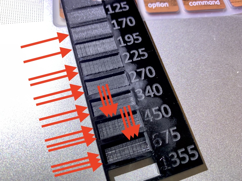
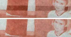
This uneven spacing in engrave passes is what we see as banding. This is less noticeable at low LPI settings as even though the lines are not evenly spaced, the rounding error is small relative to the distance between passes so they look relatively even. At higher LPI, the rounding error is much greater as a % of the distance between passes and we see banding as some passes are closer together than others. Crude Example: if the machine native LPI is as shown in red and the requested LIP is as shown in green, then the resulting output will be what is shown in the black. 11 passes as requested but not evenly spaced.

If my thesis is correct, then the simple solution would be to only offer LPI settings that are based on (i.e. increments of ) the native LPI of the forge. That would only leave the inaccuracies inherent in microstepping as a source of error which I assume are not huge.