Maybe this comes from an engineering, machining background but after the first couple of prints I was not satisfied with just visually placing files onto my materials. I also started playing with creating custom cutting boards (IKEA items) and cork coasters, so I wanted to create an alignment/setup template.
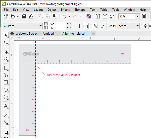
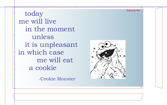
Corel Draw is my preferred interface to prepare my SVG files. I had already created a template page sized 11 x 19” for my initial workspace. I noticed while I was printing a Power test for one of the IKEA cutting boards, that every time I dropped a file into the UI from Corel, it was always in the same place. Images were located in the same location in Corel relative to the 11x19 paper size.
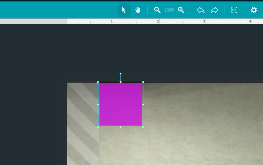
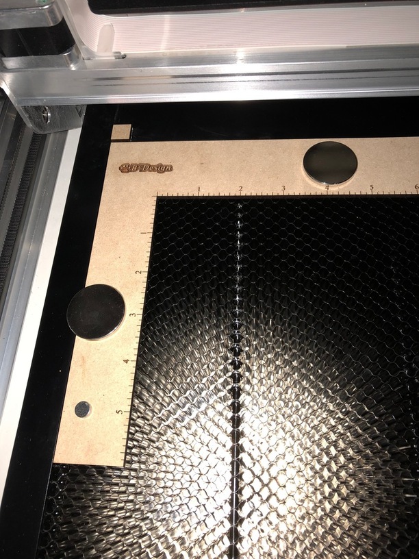
Step 1, I made a test score with a rectangle placed at the upper left corner of the workspace and marked a piece of scrap in the Glowforge (placed against the crumb tray edges left to top). I zoomed into 450% and manually moved the rectangle as close to the printable area as I could. This rectangle was set as an engrave to ensure I would always be within the workspace. After scoring the rectangle, I measured the distance from each edge to the score line.
Result:
X limit was 1.375
Y limit was -1.657
Step 2, I created and cut an alignment jig, based on the limits, and fixed it to the crumb tray.
Step 3, using the values above I created a work coordinate zero in Corel (think G54 work coordinate system) by placing guidelines at X=1.375 and Y= 9.343 (11-1.657)
Throughout the weekend, with multiple power cycling and uses, this value held. I would create/place a design in Corel and the image would align in the Glowforge and the material placed against the alignment jig.
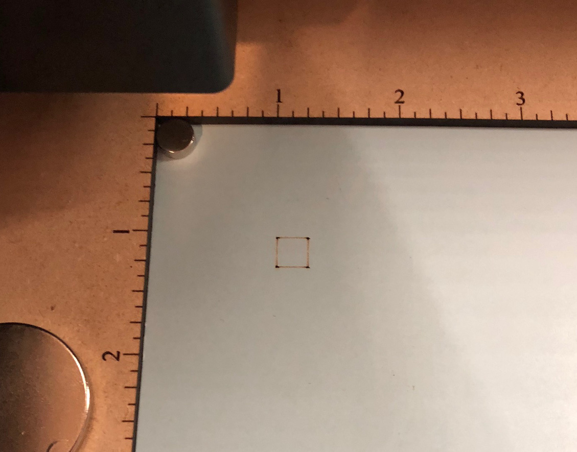
For verification before each days work, I placed a sheet of cardstock and scored a ¼” square that should be 1”,-1” from my WCS and measured the result. The coordinate values remained constant for about a week.
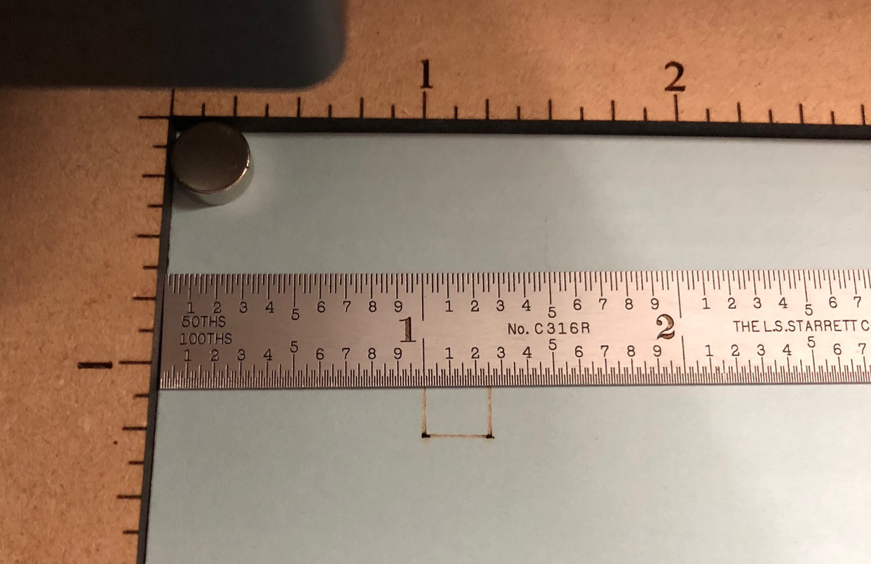
I’m guessing there was a post processing change in the GFUI, after a week, as my alignment square was no longer at 1,-1. I measured the new values and updated my guidelines to X=.069 and Y=10.944. For the next several prints days, these settings were repeatable.
Another week passed and there was another shift between my WCS and where it would actually mark the cardstock in the Glowforge. I measured the test square and my updated guidelines were placed at X=.685 and Y=10.938.
Two more days passed before I had to readjust the guideline locations. X=.596 and Y=10.963. These values have remained consistent for the last 6 days.
Conclusion. The coordinate values stored within my SVG files from Corel may be translated through the UI, but they are repeatable at the very least within a given day or worst case within a single power cycle.
When I need an accurate location in the Glowforge, I can run a quick zero test to confirm or adjust my guideline settings in Corel and get repeatable placement results for print jobs that I’m running.
I can load my artwork into Corel, position based on 0,0, and when I drop into the GFUI I know exactly where it is located without having to worry about the fisheye lens placement.
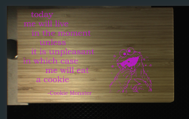
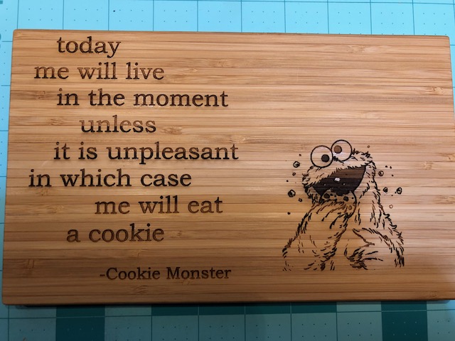
And the finished result:

 But this is a fantastic write-up and going to be a great resource for when I do buckle down and get my machine dialed in. Thanks so much for sharing!