first post here. got my glowforge (basic) two days ago (even before the proofgrade materials since i’m in the bay area). so far, it looks mostly great! been trying a couple of test cuts.
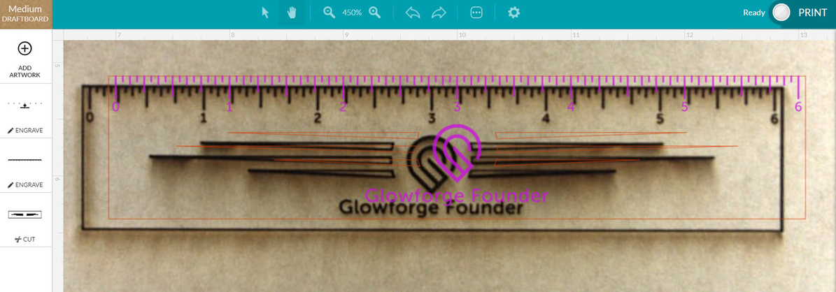
is this a cause for concern? i’ve used proofgrade draft board, made sure everything is flat, etc. but i consistently get a 1/4 to 3/8 offset (more on the X axis, less on the Y axis). will software be able to fix this? i’ve tried applying manual offsets, but that does not seem to be consistent across the bed (different corrections for different positions on the bed). i’m not sure how tracing would work well (which is how i first noticed the issue)
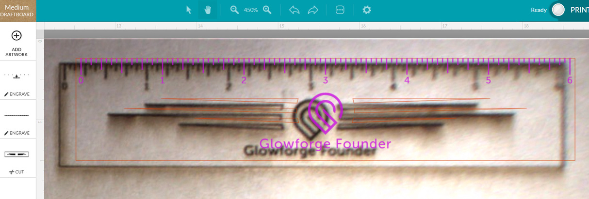
i noticed the image sharpness nearer the edges is pretty low (from my 2nd image). similar concern for large traces, too blurry to follow the traces. i also want to engrave on picture frames which are quite large and would be close to the edge of the bed. so a sharper image seems important for proper registration.
the single camera is super sensitive to the material thickness variations for areas further from the center. i guess using magnets to hold down large materials flat is important. perhaps there will be a 2 camera version in the future to eliminate the acute-angle errors.
there is a led laser spot (not round, more like capsule shaped) from the laser head to the material after pressing print and when the head goes to the starting position. anyone knows what that is for? something to do with determining the surface height of the material?
i had quite a few times where the head “crashes” into the left side (and never completes calibration), but i think that seems to be a common problem; just manually move the head to the center before powering on.
i’m glad to join the glowforge community. lots of super helpful people and posts here! definitely looking forward to cutting cool stuff
Just a couple of quick considerations. Are you sure the unit is on a completely flat surface? Is the door closing all the way?
It is not for me to call as I’m just another owner but it looks like you are right on the edge for a send it back fix. They are saying 1/4" or less will be fixed with software.
The offset is pretty normal. It is going to get better (has gotten better over the past year, still making progress). It will be fixed via software according to GF.
Image sharpness at the edges is an artifact of the fisheye perspective necessary to get such a wide view from a short distance from the material (lid to tray height). It too is getting better (and via software).
You are correct about the sensitivity to the material thickness. When using your own, make sure you measure carefully (a $12 set of digital calipers from Amazon is super handy). Magnets (most of us use various diameter thin neodymium magnets also from Amazon) are also extremely useful in making sure the material is flat. The head camera will account for variations in the future per GF but right now you need to make sure you flatten the material to the bed.
The red laser from the head is a homing and locating spot. It may be used in the future to mathematically calculate material thickness but now I believe it’s only used when homing.
The “crash” into the side is also a known (and according to Dan) benign issue. Some do it some don’t. If yours does, one way to prevent it is the manual head positioning you’re doing.
Looks like you’ve got things going okay and already picking up some of the tricks. Post your stuff here - we all love to see it.
Just to be clear, the ruler cut exactly where you initially positioned it correct? The camera image taken after an operation is known to be displaced.
As an example, if the board you cut it from has not been moved at all, you could flip the ruler over and print it again - Even though the post op image shows displacement the file will print exactly where it was placed the first time.
The offset in my post he linked to above was deemed not normal and not fixable through a software update. GF has sent me a replacement unit (have not received it yet) and asked me to return my original unit.
They weren’t specific on mine about what was not fixable, so it’s possible the offset here is different from the issue mine was having. Hard to say.
Okay. But his looks to be within the 1/4" that they’re saying is within tolerance. Are you saying that they no longer make the claim that 1/4" is not “normal” anymore?
yep. i believe it is flat, i also doubled checked that the door closes fully on both sides. my glass door is bowed/curved upwards as well, which i think is common, but i did not try to flatten it with weights.
actually, the ruler did not cut exactly where it was positioned. for example. if i cut again starting from the misaligned image in my post, the 2nd cut would be exactly where the first cut is, but still not where i planned it to be. so, you’re right the cuts are repeatable, but both with the same offset errors from planned. i can apply the appropriate correction offsets (similar to A way to improve object placement) but the amounts would be slightly different across the bed. i think the 3rd picture from this post Alignment / Fisheye help illustrates the non uniformity.
i think the glowforge currently works really well for “direct-to-print” images, where we don’t have to position precisely. one of key advantages of glowforge for me is using the camera to align with the material being cut. i had a 50w “shenhui” laser way back when, manually setting the head height and positioning with the red laser dot is such a pain. this is light years ahead! i’m just abit surprised by the rather large offset errors, which i had thought can be (camera) calibrated. hence i wanted to check if this can be fixed by software or there is some other hardware/mechanical/alignment issue.
That is different from how my machine works in lid camera photos and positioning and post print imaging with design overlay.
I don’t know if we can all agree on what is normal behavior just looking at the post print image. There is considerable variation demonstrated from laser to laser and situation to situation. As @csader pointed out, his offset issues were enough to warrant a new laser, as have others.
What browser are you using? Safari is known to have positioning errors, especially when zooming. Consensus is to use Chrome for best results with the GFUI.
There have been out of tollerance errors that were fixed remotely, and others that have required replacement.
One thing @PrintToLaser was pointing out is that alignment errors can appear worse after a cut. The GFUI seems to lose the material thickness when taking the “after” image of the bed. Thus the image of the finished cut will be de-warped using a thickness of zero, or some other incorrect value.
To get a better sense of the actual offset, try marking the material with an alignment mark, and aligning a simple crosshairs pattern on the mark. You can just do a light score just to mark the masking, or just use a piece of paper.
That will show you on the material just how far off it is.
I did some guesstimates (I don’t have mine yet so I was guessing on dimensions) that the edges are somewhere in the neighborhood of 20-25 pixels per inch.
I think the opposite. It is used with the head camera to measure the material thickness for focus when you hit print and it says “scanning”. I don’t think it takes part in the homing. That is lid camera looking for head logo.
that’s a good point, i did something similar. i had to apply offsets (alot of RIGHT, some UP) just to hit the mark on the material. otherwise, the cut will be the left and below the mark. we only know the misalignment after the cut when the glowforge rescans the bed. fortunately, getting that error is repeatable, hence i think the method described (linked above) to correct for it works, but a hassle since it is not uniform across the bed (and over different material thickness).
this might be a problem if i want to trace a large image to cut the outline, or engrave on a large photo frame and need to position the cut quite accurately i often like to engrave on “real” items (photo frames, wooden tags and pens, etc), so the glowforge camera should be really great for this,
i think so too. i tried placing a photo frame that is just a bit too thick (about 0.6") and glowforge rejected it after the “red dot” scan during the initial phase. i wonder what is the sensor technology (time-of-flight or something else). what if the felt-black material does not reflect any light?
It won’t be time of flight to be accurate to fractions of a mm. That would need to measure time in fractions of picoseconds. It just looks at where the laser beam strikes the material with the head camera and triangulates.
It won’t work if the material is perfectly black but nothing is. The black box on a test card is actually a hole into a felt lined box. I think it does get confused if the material is transparent. It relies on PG having paper masking.
The point I am trying to make, and I only know from reading the forums since I am still waiting for mine, is that the alignment in the GFUI after the print doesn’t matter.
Try this to determine the error at center of the bed under the camera:
Make a + mark in the material with a pen.
Place the material with the mark under the camera
Load an SVG with two lines making a +
Set the operation to a light score.
Align the preview so it exactly aligns with the mark. Do not try to apply any corrections.
Run the print.
Remove the material and measure the error between the pen mark and the score made by the laser.
Like some have said earlier, we’re still improving our layout and alignment, so your print may appear offset from where you put it by up to a quarter inch.
For the most accurate alignment results:
Use Proofgrade materials
Enter the thickness of the material if it’s not Proofgrade
Use material that is not warped or tilted
Place your design near the center of the bed
Reboot the machine if you see the alignment drifting