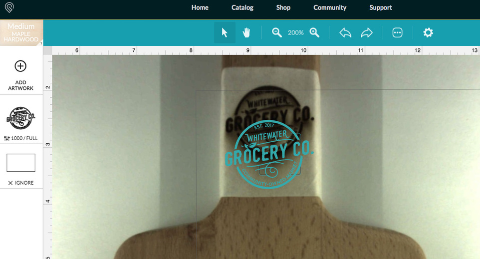
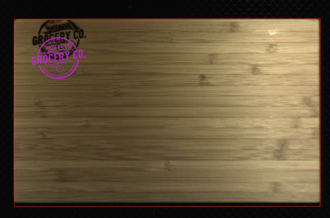
So, I’ve been through this before, and never got it resolved. (View inside appears to resize) I stepped away from cutting boards for a while because it was making me crazy. I’ve done other non-PG materials like Ikea Cork Trivets, non PG acrylic and slate coasters with no problem. So here I am, today, feeling confident that I can make my cutting boards work, after doing a couple more cork trivets with auto focus, no problem. I had done them with no crumb tray but propped up to just about exactly where PG medium materials would be. Then I did auto focus. I did two types of cutting boards, and the result was exactly the same (even though the boards were slightly different thicknesses). They shifted up about 1/2 inch. I didn’t take a picture of the first one, which was a small Ikea bamboo cutting board, but here’s a small beechwood paddle board.
That seems odd in that the offset is vertical while the horizontal alignment seems fine. The only thing I question is whether the set focus beam actually fell completely on the material.
If you’ll look closely, you’ll see the focus box on the handle, but here is a picture I’ve recreated of the other board. Here again, I clicked to focus right where I wanted the logo, and the focus square stayed in that approximate location. Also, in the case of this board, I have an ignored cut line that I use to line up the board to make sure everything is in position.
One thing I see a lot is people putting in a PG material when it’s not PG.
What’s your process for this? Are you using set focus, then picking a material? Picking a material and then using set focus?
I could see the vertical alignment only being off in this case since you are basically right at the midpoint of the machine (horizontally), I believe, if perhaps you picked a material after using the set focus tool.
Have you powered down the machine between those two different runs? Does the issue persist after a reboot? How tall is the material?
If I didn’t set a PG material, it wouldn’t give me existing presets, so I set the material, and then I set focus.
The material was set at a height of about 1.55 and I did not power the machine between these, but I have in the past when I was trying to correct this, but it didn’t make any difference.
I would add another layer to the drawing in the form of a simple crosshair, with the center of the crosshair in the center of your artwork. Then, I’d put the cutting board in the GF and tape a piece of paper over the area to be engraved. I’d disable the artwork and enable the crosshair and do a low power score to imprint the crosshair on the paper. Then, I’d measure the offset from the crosshair to where I wanted the artwork to be. I’d remove the piece of paper from the board, go to the GFUI and move the artwork the distances required based on the measured offset of the crosshair. Then I’d disable the crosshair and enable the artwork and engrave.
propped up to just about
That’s the problem. “Just about” isn’t good enough. The offset is only in the vertical direction because the cutting board is at the center of the machine. If you moved it to the left or right front or rear corners the offset will increase and be visible in both the X and Y.
The GF camera is a very wide angle lens. The image from the camera is severely fish-eye distorted. The GFUI does some math on the image to “flatten” it but it can’t do anything about the fact that areas further from the lens are being viewed at a more oblique angle. Small errors in the math are magnified for those areas. You tell the GF how thick your material is in order for it to do the flattening math. You may notice the zoom of the bed image changes when you change the thickness in Uncertified Material, because the transformation to flatten the image is dependent on how far the lens is from the object. When the GF is told that the distance has changed, the flattening changes, too.
What this means is that if you don’t tell the GF exactly how thick the material is (really, it’s how far the surface is away from the lens but it’s reverse-referenced to the top of the Crumb Tray), the math that flattens the image is going to be wrong. Near the center of the lens the error will be small, non-existent directly beneath the lens, and further away the error will be worse. If you figure out exactly how high the surface of the cutting board is, instead of just about how high it is, I bet the problem goes away.
So, the first time I had this problem, it didn’t matter if I exactly measured and input the height (being total height of materials including props - crumb tray height), or just did auto focus. When I say it’s “just about” I was using a no measure tool, and I have an additional line showing exactly where my medium materials come to, and it was very near to that, in addition to being well within the acceptable range. While the steps you describe certainly sound like they would resolve the problem, it’s my understanding that if you’re within the designated range, then either doing set focus, or inputting the height is supposed to take care of all the math. I see pictures of people using these materials all the time, and they are not going to such great lengths.
I see significant changes in the size of the image in the GFUI with as little as 1/16th of an inch difference in what I tell it the height is. The autofocus works for focusing the laser, and the GFUI may indeed get the thickness information to adjust the image being displayed. But by then the print is running. I don’t see how autofocus can help you before you start the print, which is where you’re having the problem getting things aligned. It’s certainly possible there’s stuff about the GF I don’t know. When I got my GF the camera was completely undependable. I developed a workflow that only depends on the camera for the grossest of alignment tasks. So I haven’t really taken a close look at the autofocus stuff.
Set Focus should, in combination with having run the camera calibration, be as accurate as you get. More accurate than entering in the exact material thickness/height actually.
The Set Focus tool basically moves the material scanning up in the process. Rather than it happening when you hit print, it goes to the area that you select, measures the distance from the head to the material, and sets both the material height field and the autofocus for the lens.
Agreed about the small difference in height making a big adjustment. I have a GIF around somewhere showing the difference that just 1/32” makes.
@jeffmik05 - personally, I’d try to just use entirely manual, uncertified material settings. You’ll get more familiar with those as you go, and/or you can save certain things as presets. By selecting a PG material, I know you’re getting the presets, but you’re also getting a specific material thickness. It just seems like something else to go wrong.
The measuring beam for set focus is usually a bit offset from the center of the square, but it should fall within the square. That doesn’t seem to be a problem here.
One thing that might be worth checking is that the windows on the bottom of the head are both clean. One is a camera, one is a diode laser. It uses the camera to capture where the diode laser falls. Have you physically verified that the red beam is emitting from the head? One possibility is that it could be defaulting to the PG material height if it’s having trouble capturing the material height?
While it sounds like you’re having to do a lot of extra work, you probably also save a lot of materials! I have a digital caliper and have entered that exact measurement and not used the auto focus when I first started having this problem, but it did not make a difference then. I am just assuming it wouldn’t make a difference this time as well, but I am also done with this issue for tonight. I would just like my machine to work the way it’s supposed to, and the way it seems most do for other people. I’ll try again with the calipers tomorrow to see if I have any different results.
I’ll go ahead and try having manually set material information tomorrow, although I’m pretty certain that was one of the things I tried last time. Then I’ll have it masked and do a light run to see where it ends up. I did clean all the lenses between the two materials tonight. Thank you for your input.
I would definitely use manual settings and I rarely go with just one “Set Focus” but run it several times. You can also include a “test” setting (I have it saved in Score) on an outside of your shape top speed and minimal power and it will not make it through the masking but tell you exactly where the design will land.
I’m so sorry to hear that you’re running into trouble. I appreciate you sending over all of this great information.
I’d like to see if the same alignment trouble occurs with Proofgrade material and default settings. We’d like to have you try a few troubleshooting steps for us:
Turn off your Glowforge.
Check for small pieces of debris or dust.
Check the lower door to make sure it closes all the way. It may require some force to open, but open it, wipe any dust off the edges, and close it all the way.
Remove the tray and clean any dust or debris from the surface underneath. Pay careful attention to remove all debris from the four dimples where the tray rests.
Check the lid to make sure it closes all the way. Small particles of material, such as dust or debris, can prevent it from closing completely.
Check the surface your Glowforge is on to make sure it’s flat. Ensure it is not twisted slightly and that there is no debris propping up one side of the machine.
Turn your Glowforge back on.
We included an extra piece of Proofgrade Draftboard with your materials shipment for troubleshooting. Place the Proofgrade Draftboard in the center of the bed and print the Gift of Good Measure using the default settings.
When the print finishes, leave the lid closed and wait until the fans stop and the picture updates. Without moving your artwork or your material, take a screenshot of the Workspace to show us the difference between the artwork placement and the actual print placement. Make sure to include the rulers in your screenshot and show as much of the bed as possible.
Mac: Press Shift-Command-4 and click and drag a box around your image. You’ll find the screenshot file saved on your desktop.
Windows: Click on the Start Menu and type “snipping tool”. Open the Snipping Tool > New then click and drag a box around your image. Click the Save icon and name and save your file.
Send us the screenshot along with the date and time of the print, and we’ll investigate.
It’s been a little while since I’ve seen any replies on this thread so I’m going to close it. If you still need help with this please either start a new thread or email support@glowforge.com