I am curious if anyone has had any luck with using Fusion 360 to engrave and cut a design. I have watched the Fusion 360 training videos, I use Fusion 360 for 3D printing and CNC milling, so I know it. My problem is that when I try to create a file that does cutting and engraving in Fusion 360 Laser is only wanted to be used for cutting, not engraving. So I cannot create a cut path.
It is possible that I don’t even need to be doing this, maybe the magical web gui does this for me. But at least I think we need a video of JUST taking something from Fusion and putting it into the web gui for cutting. I don’t have my laser yet, so I can’t get into the software. But I would like to be able to use what I have made in Fusion 360 on the glowforge, and would also like to start making some new files as well.
Haven’t tried to use F360 for engraving directly in the GFUI.
Tell you why - The way that Fusion 360 exports a DXF file it can frequently contain disconnected segments…especially if there are any complex curves associated with the file.
We have to take that DXF file into a 2D vector program anyway, (such as Illustrator or Inkscape), in order to convert it into an SVG file that the GFUI can use. While it’s in the 2D vector program, you can assign a Fill color to it, and that Fill color is what the GFUI sees and engraves.
I’m not sure what it would do if you tried to convert a bunch of disconnected lines into an engravable area with the GFUI, but I suspect the results might not be what we expect.
So just create the fills, and turn off the stroke color for the engraves in the 2D design program before saving the SVG. Then the GFUI will engrave exactly where you want it to.
Fwiw I think manipulating fusion drawings in Inkscape is easier than trying to do it all in fusion. Inkscape makes it much easier to get your engraved set and you can import the dxf with dimensions intact. I’ve been doing 100% of my designs in fusion and 100% of the clean up in inkscape
I am a heavy Fusion 360 user and I am a little dissapointed that DXF isn’t available yet, but I hope that will change. I did however stumble upon a Glowforge Post Processor plugin for Fusion 360 a while back that looks like it would solve the problem of having to export and convert it to an svg. http://cam.autodesk.com/posts/?p=glowforge
It seems like it would be pretty intuitive for more advanced cnc/cam guys. Not as elegant as the glowforge UI, but it would save a step.
It was published back in 2015, so I am a little curious if it is currently usable? @dan
In F360 try the workflow:
Start new sketch
Select surface that you want to define as the DXF cut path.
STOP sketch
Go to browser, search for the most recent sketch
right-click on it
Select SAVE as DXF
Save the file where you want it.
This will create a DXF version 14 file.
I don’t know how the GFUI interprets F360 DXF files as my Pro unit is not yet arrived.
A little experience:
A client of mine has a junky laser cutter, the software likes to import the DXF files in a strange way, the result is that groups of entities are mostly ignored (disappear), so I go to Adobe Illustrator and ungroup the entities. Then export as DXF V14. His software then interprets the entities and the outline shapes become useable again.
Last thing, the DXF files are imported into Adobe Illustrator in the negatives quadrant, so I move them over to the positives quadrant.
Main issue I had was with splines. Luckily, there is a spline to polyline converter that seems pretty popular. Just run it when you’re ready to go and use the dxf file it generates (this was with other laser workflows I mean). Never had an issue with disconnected lines (that honestly sounds like an issue on the designer side, no offense)
Ah-Hah! I knew it! (That explains rather a lot, actually.)
No offense taken - it’s definitely caused by a design side issue. A lot of beginners try to use automatic slicers and box generators instead of designing their own connected lines, and those haven’t been real consistent with joining the segments. (Sometimes yes, sometimes no. Depends on the program. The Slicer in F360 doesn’t join them consistently.)
Easiest quick fix it is to do it in the 2D programs with a join before you save the SVG.
I use a few CAD Apps, one of them is called SharkFX. There is a 2D tool in this App that converts planer 2D splines to several ARCS that are tangent to each other at their end points. This tool has helped make several files useable by different vendors for different jobs over the years.
I forgot to add that for some reason a grouping of entities can also cause lines and arcs to disappear, either partially or fully. So, I always have to check in Adobe Illustrator to see if there are groups to ungroup before sending to vendors.
That is a unique outlook, everyone else is wanting the GFUI to take DXF directly. BTW, you know the drawing section of F360 will output PDF right? And the GFUI takes PDF.
My desire for SVG output is driven as much for the need to be able to import into Inkscape as much as my desire for input to the GFUI.
I prefer to do most of my design in Fusion. The ability to extend/trim lines, create circles at precise points, essentially the drafting features that are lacking in so many illustration programs. Creating circles by dragging a bounding box is so 1984…
But Inkscape can do fill and text, perspectives and a lot of things fusion can’t, so I often go back and fourth between them, with more success sometimes than others.
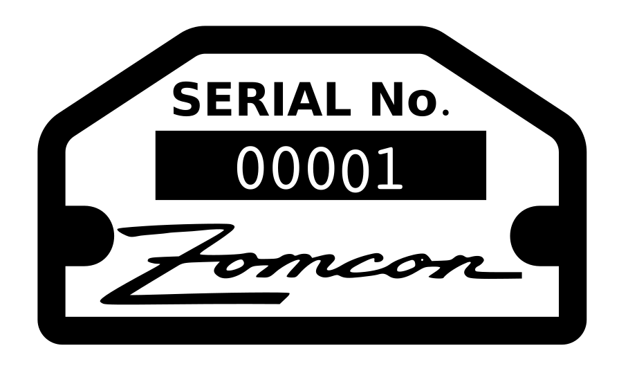
These are two examples of things I do on a fairly regular basis.
This first logo was designed in the early 80’s so no digital files were ever made of it.
I took a scan of the best copy I could find, Color separated it in Gimp, took each color and converted from bitmap to paths in Inkscape, asked as SVG and then imported to Fusion. In fusion, used the Cad features to clean up the lines on the B, and re-drew the roads. (They are now symmetrical for the first time), Exported as DXF, then imported back into inkscape for final cleanup and filling in with color.
The second example is something I will also be doing a lot. the border around this tag is far easier to create in Fusion, than in Inkscape. It also needs to be a precise size, in order to fit in the recess created for the tag. The Zomcon logo was also converted form bitmap to Paths in Inkscape.
i’m not sure what you mean. i can’t comment on the 3D/CAD programs, but certainly Illustrator and Corel have been able to do this for as long as I can remember. Select the circle tool, click on the location you want the center of the circle, type the dimensions into the dialog box, a circle at those exact dimensions appear at the location you chose. there may have been a point you couldn’t do circles exactly like this, but if so, it was so long ago (i go back to illustrator 88 and corel 2.0) that i’ve blanked it out. and bezier points have been capable of extending/trimming lines for sure since at least illy 88 and corel 2.0.
 - I use it for those same things as well.
 I followed his instructions, it’s worked out perfectly (thanks again!)