I’ve created this topic to showcase instances of good lid camera alignment. We’ve seen plenty of bad alignment cases, let’s see how good it can get!
Suggested submission format:
–Find an old piece of cardboard or chipboard that covers the whole bed.
–With a dark, fine-line pen, draw a bunch of random shapes or test patterns all over it, out to the edges.
–Put the cardboard in the Forge.
–Read the test patterns with the lid camera.
–Select those that fall within the printable region of the bed.
–Engrave the test patterns lightly, right back on the same piece of cardboard (without moving it).
–Post an image of the result, e.g., either a screendump of the GFUI, or a simple photo of the cardboard showing the drawn patterns and the engraved patterns.
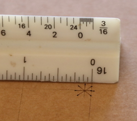
–Be sure to give some indication of the scale of the result. What we’re looking for is the maximum distance between any test pattern and its engraved version. You can, for example, measure it with a ruler and write that measurement on the cardboard before photographing it.
Can I suggest we use a standardized test pattern to better compare apples to apples? If you feel like making one, I’ll do the requested test since I’m one of the people claiming to have good alignment.
I submit the design itself doesn’t matter at all. What matters is the offset. And when posting any result of this, it should be noted if it’s an engrave or score as I’m not sure those results will be identical. Also any result should include the rulers and magnification level so it’s clear what you’re seeing.
Alternately, of course, one could “print” onto blank cardboard with the laser, then scan it back in and print again. If the file is the magic full-bed size, it will be in the same position on everyone’s machine. We should also be sure to use the same material height and engrave settings.
If you’re going to do a comparison, you really want to control as many variables as possible.
That might work, too. The laser-created markings on the cardboard would have to be dark enough to get a good camera scan of them for subsequent re-printing.
It seems @Tom_A has a procedure that could be standardized, too. I’m not sure I understand the details of how he does it.
I may just start with a big image of a ruler. Then I can compare the original ruler to the scanned ruler to the printed ruler to the re-scanned-and-re-printed ruler… top, bottom, left, right, and middle in both axes. I’d also like to see how “incorrect” material height affects those results, and maybe even offsetting the lid slightly.
I wouldn’t call it a procedure. I just did what I thought made sense.
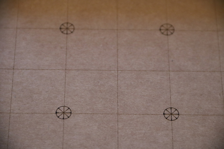
When testing on cardboard I used bed-sized cardboard flattened with magnets. I put a raster of a ~1" x ~1" targeting reticle dead center (as visually aligned with the rulers in the GFUI), and in each corner, and roughly center of each edge, then sprinkled a few more throughout the bed as well just to see a little variance. YOU SHOULD EXPECT offset at the extremes. That’s guaranteed. The amount of that offset is likely to vary machine-to-machine. But dead center should yield near-0 offset since it’s directly below the camera.
When testing on Proofgrade, I didn’t want to waste any, so I used some scrap I had and moved the, in my case 4", scrap around the bed, and then targetting it in various places similar to the cardboard and grabbing a shot with the Snipping Tool for each one.
Again, I don’t know that much of it matters. I think the real test is the center-bed test. Can you NAIL it? Does it hold up at >100% magnification? In my first machine I could hit a 1" x 1" piece of material with… well… laser accuracy.
That is simply not going to be possible at this time. Literally not possible. For the claim to be valid, center bed.
I think you’re helping explain why we need to agree on a test pattern in advance. Otherwise this thread will be full of people nit-picking why any given set of marks isn’t a good test.
But to be clear, what I’m talking about doing would be kind of like this, which I think captures the whole bed:

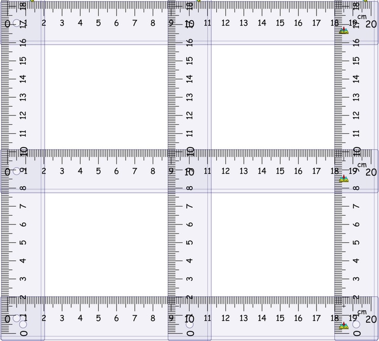