I have to believe this is doable, but my knowledge and internet searching is failing me, so I’m hoping someone here has done this and can help.
I’ve designed a relatively complicated box in Fusion 360 and have successfully used the Colorific post processor documented here:
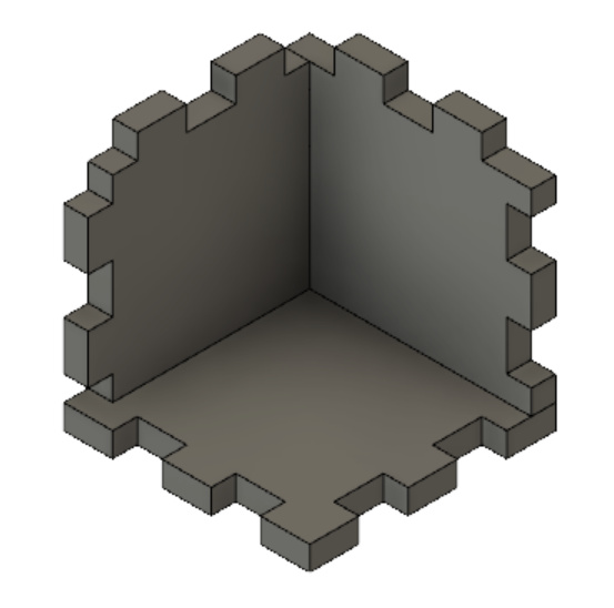
to create all of my tool paths for the cutting of the parts. (Pictures will come eventually when things are assembled.)
The next step was to cut some adhesive backed felt for the inside of some of the parts of the box and I’m stuck on how to create the right tool path since everything I try really wants to select the face of a body and doesn’t really handle the idea of the paths of the intersection of bodies.
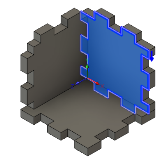
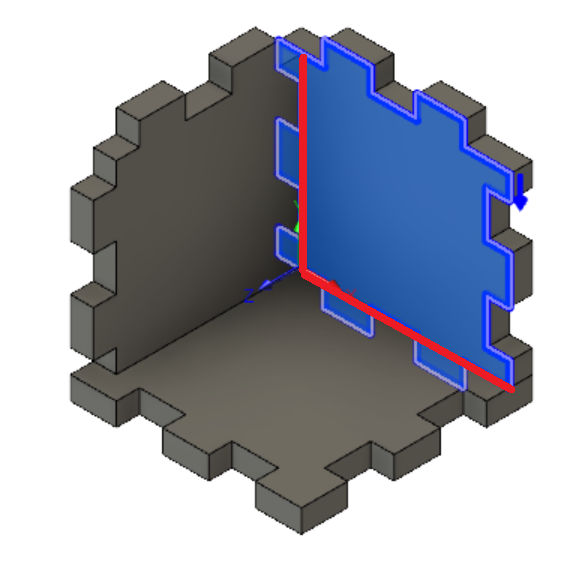
But I want to create the path that doesn’t have the fingers hidden by the other bodies (remove the parts outside the red line and cut the red line instead instead):
In the contour selection part of the toolpath creation, I can select the intersected edges, but I can’t combine them with the rest of the body path without getting all of it (a union of both red and blue paths).
Now, obviously, I could relatively easily do post-processing work in Inkscape on the path from the body to cut off the fingers and will likely do that if I can’t figure this out, but given the number of parts that is going to be a bit error-prone so I’d rather have Fusion do all the tedious work. (The other thought I’ve had is to just add the felt as a component of the model, sketch and extrude all the pieces, and then create the paths, but again, I was hoping for something simpler.)
You have to create a sketch or body with the path you want. You can easily create a new sketch on that face, draw a rectangle and constrain the borders to the inside of the box. When you create your CAM path, select the sketch instead of the body. I’m sitting on an airplane about to take off, so I can’t post pictures for you.
Ah - didn’t think of trying to just use a sketch! That is a bit less work than creating all the bodies, so that will likely be good. I’ll give that a shot tomorrow.
A quick follow-up: this worked pretty well - only interesting quirk is that the sketch needs to be “clean” (no extra lines/pieces) since unlike the extrude step from a sketch where you pick the sub-parts of the sketch you want to use, the toolpath will be the entire sketch. Other than that, I’m off and running!
@jeffreykrauss, I can give you a more elegant workflow. Would you mind sending me your file? I’ll make a video showing you a nice workflow and post the video here. Using your file will make the workflow as realistic as possible. Send file to me in a private message.
I think my real file is a bit too realistic to make a good example, but I can probably simplify it a bit without making it too much of uninteresting test case like my kerf test box I used to illustrate in my original post. Give me a day or so to see what I can pull together…
I realized a simple but real example is to use the tray component from the overall box with a bit of the complexity removed since it should have all the same challenges. Here is the .f3d file - if you’d prefer another format, just let me know.
@jeffreykrauss,
I made you the video I promised. I hope you enjoy it and learn a few different methods to achieve what you were hoping. As a bonus, I also talked a little bit at the end about the differences between bodies and components and the advantages of designing components instead of bodies.
Here is a link to the video: https://autode.sk/2BYJsD6
Cheers,
Jason (@Secret_Sauce)
I’ve never played with the sheet metal commands and that is a really neat method for this - I’ll definitely play with that next at least to understand it better.
Also thanks for the ideas on making more of the bodies components - I have used components for the various parts of the larger box (like the tray itself) but never thought to use it for these parts, for some reason.
(Oh - and apologies for the parameters confusion - when I copied the component to isolate it, I didn’t think of deleting all the extra parameters - I’ve also learned a lot since I started this project and would probably use a slightly different set of parameters.)