Hello. I am sure this is here somewhere, but I am struggling to find the definitive workflow that shows how to get a drawing from Fusion360 to Glowforge. I know how to export a DXF, but I can’t seem to import it into illustrator without it coming in huge.
If you could explain the detained workflow so I can get the design in the correct dimensions into Glowforge, or point me to the right place, I would be much obliged. Thanks.
I haven’t figured out exactly where this goes off the rails, but the same happens when importing into Inkscape.
Sometimes.
Exported DXF from Fusion360 only sometimes has the dimension data embedded. When it doesn’t, you get a huge model.
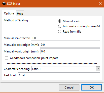
For Inkscape, I found that setting the scale to manual and leaving it at 1 would cause it to import at the right size when the imports were showing up as gigantic when trying to use the scale from the document.
Hopefully, someone with more of a clue can chime in. In Illustrator’s import, if you can set the scale, try doing so and simply setting it to 1:1.
I don’t think there is a definitive. I use three different methods depending on what I’m doing. Sometimes I use the “Save DXF for Laser Cutting” plugin when I want kerf adjustment, sometimes I “Create a Drawing” from my model and save that as PDF and sometimes I just right click on the sketch and save it that way (particularly if there are cut lines that aren’t represented in the solid, like living hinge cut lines).
My most used workflow is:
Create a sketch
Extrude into a solid
Create a new sketch on the top surface and project the face onto it along with any other cut lines I want from the original sketch (this avoids having to trim out construction lines in Inkscape)
Then I:
Right click on that last sketch and save as DXF
Import into a fresh Inkscape document using the following settings:
The shaper plugin at least gets us from 3D model face to correctly scaled SVG with properly linked paths in 1 step. But its missing the ability to color the parts of the SVG differently to make separate operations easy in Glowforge.
I wonder if the right solution is to build a CAM “POST” processor for the Laser CAM feature in Fusion 360. This would give us the paths we need with kerf compensation provided by Fusion. It would also allow us to color the paths in the SVG differently for each CAM operation. Say you want to cut holes in the part and then cut the perimeter. You can do that as 2 separate ops in the CAM workspace and the POST can detect that and output an appropriate SVG.
POSTs are just Javascript. SVG is just text: https://en.wikipedia.org/wiki/Scalable_Vector_Graphics
The only tricky thing is converting from curved line segment gcode to curved polylines in SVG. Some research is required here but I think it could be a fun project.
Early on there was exactly such a thing. I could never get it to work. Jason (@Secret_Sauce) from Autodesk has done some webinars for Fusion 360 to Glowforge, and if I recall correctly, started out with that workflow but for various reasons I think we all moved to the export plugin approach. Maybe he has more technical insights as to why.
The current Glowforge post processor just creates an SVG. It does include kerf compensation if you set up your “tool” to have the correct kerf. However, it does not color each operation differently. So, you would still need Illustrator or Inkscape to separate out each operation.
I admit that the post is not ideal. When it was written, the Glowforge people were too busy trying to deliver units to help us. If you recall, the product was a tad bit late to market…
I like @gareth 's idea of a custom post that would color each operation differently. If that worked, you could go straight from Fusion 360 to the Glowforge web interface and skip Illustrator or Inkscape entirely. That is assuming, of course, that your design includes vectors and NO bitmaps. If you have bitmaps, you will surely have to use Illustrator or Inkscape. @gareth, if you write the post, I’ll help you get it into the Fusion post library!
In the meantime, I save out my sketches as SVG files and then import into Illustrator. I do not ever have scaling issues because when I import, it asks me the units and the scale. I choose mm and then make sure it is set to 1:1. The result is perfect every time. In Illustrator, I lay out my parts and color my operations. I am using a template that is set to the max size I can cut in my Glowforge. My template also has 9 different solid colors I use to separate everything out. The colors are set to be visually distinct, which is why I only have 9 or so.
This sounds encouraging, no real deep technical reasons this cannot be done. I agree about raster graphics, thats not something I think would be supported and not usually something you care so much about that you would model it in Fusion 360.
There is certainly more user overhead in creating CAM tool paths but once thats done the round trip time from the model space to to the Glowforge is much quicker.
The current Glowforge post processor just creates an SVG.
My plan was to detect OP changes and simply cycles through a set of preset visually distinct colors in (black, cyan, magenta, yellow, red, green, blue etc).
Once it works better than the current post, I’ll submit it internally and have the current post replaced with yours.
I’ll send you a private message with my Autodesk email address.
-Jason
The existing post does all of the heavy lifting to generate lines and arcs in SVG format. All I had to do was implement the color cycling and clean up the output so each time the laser gets switched on its a continuous path element in the SVG. No more laser hopping around between line segments. Glowforge doesn’t have a “planner” yet so this is basically gonna let Fusion 360 be the planner.
The post has been sent to @Secret_Sauce for testing.
Ok, I’m starting to get excited! Here are some sample SVGs I’m generating:
2 ops, one to engrave the bullseye and one to cut the square
3 ops, 1 to cut the holes, one to cut the perimeter and one to engrave the entire shape
This is what I have implemented so far:
Each operation gets a unique color taken from 15 high contract colors from the original Mac 16 color pallet. Glowforge automatically splits different colors into separate operations.
Join cuts from each operation into a single <path> element so you don’t have to join them yourself in Inkscape/Illustrator. Everything drags and drops together in the Glowforge UI properly as a single shape. Shapes inside shapes work properly as well.
If you use the ‘Etch’ or ‘Vaporize’ laser power settings in CAM the post will generate filled shapes instead of lines. These are automatically detected as Engrave ops in Glowforge. So if done right you wont have to change anything in the Glowforge UI.
Checking for Sideways Compensation: ‘In Control’ is now off by default. This was super confusing for new users as it resulted in a cryptic error using default laser CAM settings. For most uses the lack of Sideways Compensation wont matter. For power users that want sub mm accuracy you can enable Sideways Compensation: ‘In Computer’ and this will calculate the proper path offset based on the laser kerf diameter you set up in your laser tool. There is a parameter to force checking for this (its off by default) so if you are in a production shop the POST will validate that you did everything right before it burns your last piece of material.
Each CAM operation is wrapped in a group (<g>) in the SVG and gets a <title> so you can read the source and see where the code came from in CAM. If you have an SVG and want to delete or re-order something its easy to find.
I’m still working on the stock setup. This has to be just right or the SVG looks off center (but still imports into Glowforge OK). You want the stock origin in the lower left corner with the Z coming up out of the material. I’m going to see if I can just make this issue go away.
If you are brave and want to try it out, the post is here. (when this gets accepted by Autodesk I’ll change this link to point to the official source.)
Stock point location issues solved. You can use any stock point now but you need to get the Z orientation right. If your SVG comes out upside down there is now an option in the post to “Flip Model” which will fix it. Its because your Z Axis is inverted.
I just had to write this comment:
/*
 * Compensate for Stock Point, SVG Origin, Z axis orientation and margins
 *
 * The *correct* stock point to select is the lower left corner and the right Z axis orientation is pointing up from the stock towards the laser.
 * But to make the learning curve a little gentler we will compensate if you didnt do that.
 *
 * Stock Point Compensation:
 * First, any stock point will produce the same image, here we correct for the stock point with a translation of the entire SVG contents
 * in x and y. We want to use the extents of the X and Y axes. Normally X comes from the lower right corner ofthe stock and Y from the
 * upper left (assuming a CAM origin in the lower left corner).
 *
 * Y Axis in SVG vs CAM:
 * If we do nothing the image would be upside down because in SVG the Y origin is at the TOP of the image (see https://www.w3.org/TR/SVG/coords.html#InitialCoordinateSystem).
 * So normally the Y axis must be flipped to compensate for this by scaling it to -1.
 *
 * Incorrect Z Axis Orientation:
 * If the user has the Z axis pointing into the stock the SVG image will be upside down (flipped in Y, twice!). This is annoying and is not obvious to fix
 * because X and Y look right in the UI. So the "Flip Model" parameter is provided and does *magic* by turning off the default Y flipping. Now the Y axis is only flipped once
 * like we need for the SVG origin. But the *lower* box point has to be used to get the Y extent in this case because the *CAM* is upside down (CAM origin is top left corner).
 * Unfortunatly the stock point selection changes the ratio between Y values in the upper and lower stock points, so its impossible to detect this without assuming a stock point.
 * So this is as good as we can do.
 *
 * Margins:
 * Add 1 magin width to these numbers so the image is centred.
 */
FWIW, there at least used to be some weird limitations and issues with SVG transformations that tripped up the Glowforge software (e.g. I think I’ve isolated one cause of “We’re sorry, an error occurred while preparing this print”). It doesn’t look like your code exercises any of the transforms-of-death, but I thought I should mention this in case you run into similar weirdness at some point.
I thought those were mostly fixed but I wonder if that’s a part of the problem @polarbrainfreeze is having with the Inkscape connector function. I noticed in the code it’s using a transform for at least some components.
I was throwing together a quick power settings test by copying a CAM op and I saw some strange re-ordering in the Glowforge UI of the ops that I created. They worked fine but were out of order from what they were in Fusion 360. This needs more investigation.
I also experimented with trying to explain “score” cuts to Glowforge but there doesn’t seem to be a way to do this thats officialy supported. Dashed lines seems like the most obvious way to do it but those just produce an error in Glowforge app.
So we cant force a color order to put dissimilar colors close together . I added a color sorter function so you can customize the POST with your own colors and they will be sorted and work correctly without having to do it manually.


 . I added a color sorter function so you can customize the POST with your own colors and they will be sorted and work correctly without having to do it manually.