I deliberately avoided this one, because it stretches the limits of what the machine can do with a Pro model, and Snapmarks…and you have a Basic machine, without them. And you are limited to an 11" working height. With a Basic machine you are also limited to 18 inches square on your material size that the bed will hold.
The problem with splitting a file in Illustrator is that it more often than not, leaves that little single one-pixel-wide row blank between the tiles, and you can’t even see it. Plus you are moving that around to fit the images into the printable area…
But I do love a challenge, so here is what I’d attempt to do if I had your machine, and it’s going to look very strange at first, but the logic should hold out.
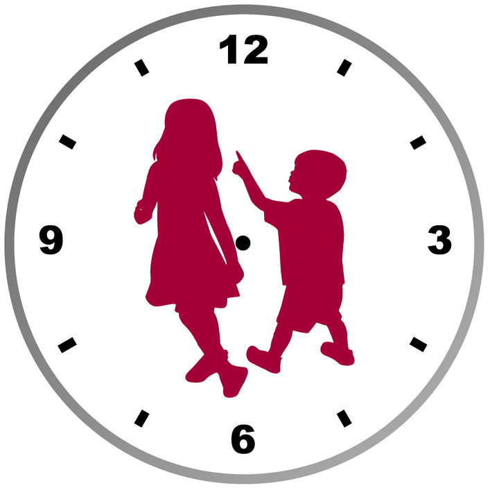
Make the children two separate engraves. (Different color fill on each) but then do not split them. Rotate the whole clock 90° in the design, and the children should be printable in one go. So no splits in the silhouettes. In addition, break up the colors on the numbers as shown below, and make the little center circle a black stroke with no fill color. I would also attempt to work a white break into the design on the circle - there is no way to get that printed on a basic without the pixel gap that I know of, so try to make it work for you, or just drop the gray circle from the design. There are reasons for all of this, discussed below.
…
After you get the colors separated as shown, you’ll be working with two “halves” of the clock. Each half should be well under 11" tall on an 18" clock face, so the “halves” do not have to be perfect halves so to speak.
You will need to adjust the file so that the file for the top half, and the file for the bottom half occupy the same space, and are oriented correctly relative to each other. First make a copy of the black stroke center circle directly on top of itself. (CTRL+C then CTRL+F). Change the color of the copy to purple stroke immediately. Then create a group by combining the blue numbers, red boy and purple stroked center circle, along with the bottom two gray circle bars for the outline, and right click, then CTRL+G.
Select that group and send it to the back of the stack so that the black center circle comes to the top. (Select the group, then CTRL+right brackets key.)
Next group the top half objects together. Select the green girl, the orange numbers and the black center circle. Do not select the gray top half circle segments, you don’t need them, and they can be deleted. Group the other items together - right click and CTRL+G.
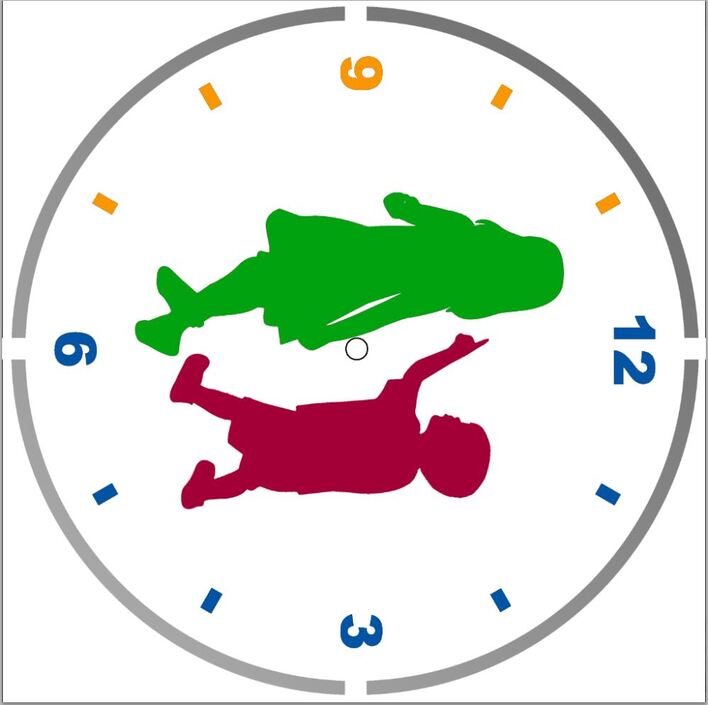
Now, because you will need to rotate the material in the bed to be able to print the top half, you need to rotate the top half design by the same amount. Select the group, rotate it by 180° (in the Transform menu), and then align the little black center circle exactly over the top of the little purple center circle without ungrouping anything.
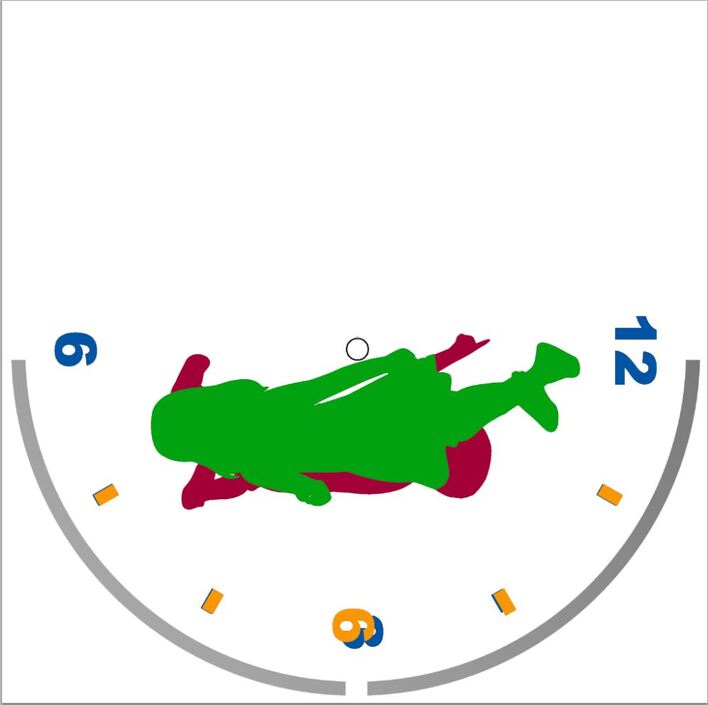
Your file is ready, and it should look something like this when it’s done:
Here’s how to print it:
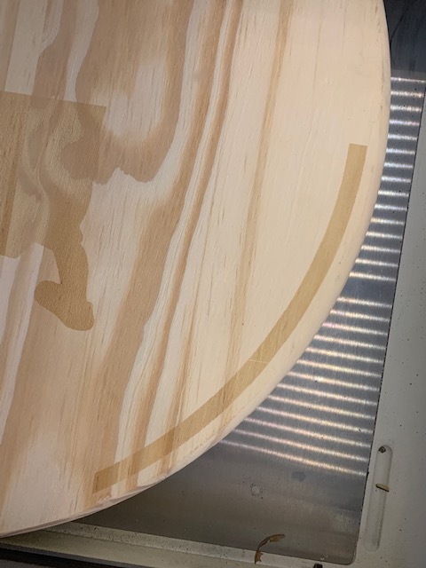
Start with perfectly square (or round) material, it has to be rotated essentially in the same place relative to the front door, so you want to get the design actually centered as much as possible on the material or your center point will rotate out of range of what the machine can reach. Put some white masking tape in the center of the clock face, you’re going to score for placement and you don’t want to mark up the actual wood.
Put the material in the bed, close to the front of the grid. (Should completely cover the gridded area of the tray, but not overextend to hit the door.) If it’s round, find a way to anchor it at the sides so that it can be turned in place without shifting it too much. (Something to brace against.)
Engrave the bottom half elements - gray bars, red boy, blue numbers and score the center purple circle at a low power (10%). Everything else should be set to Ignore.
Process that, open the machine and rotate your material 180° counter-clockwise. Try to keep it in the same place on the bed if it’s round.
Set all of the bottom half objects to Ignore in the thumbnail column. (At this point, every operation needs to be set to Ignore.)
Find the black center circle from the top half of the clock in the Thumbnail column and set it to score. You will need to shift EVERYTHING in the file until that black circle scores right over the top of the purple circle score that you did in part 1. Select everything by pressing CTRL+A on the keyboard, then shift everything together using only the arrow keys on your keyboard. (SHIFT+ Arrow will jump it farther in a certain direction) Do not try to drag it, you will resize something along the way.
Using the arrow keys, shift the whole design until it appears that the black circle is going to score right over the earlier score. Run a test score at lower power (10%) for just that circle to see if it lands exactly on the earlier score. If it does, great, proceed to the next steps. If it doesn’t, select everything again (CTRL+A) and shift it a little bit with the keyboard arrows. Try the score again. Keep doing that until it’s an exact match, it will align the parts correctly.
Last part, once you get good repeat on the score, you can change the Score for the black circle to a Cut. Process the Engraves for the green girl, the orange numbers, the two gray circle parts, and the Cut for the center black circle.
Piece-o-cake, right?