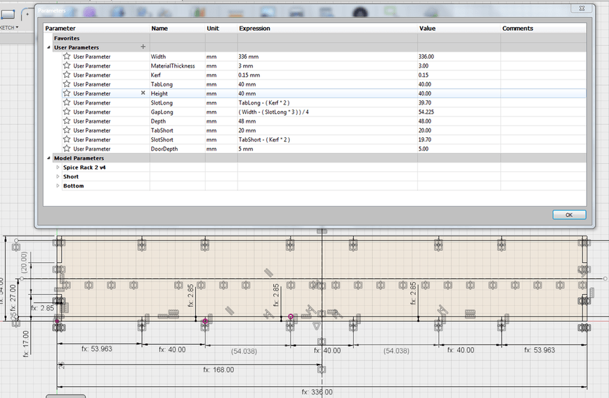
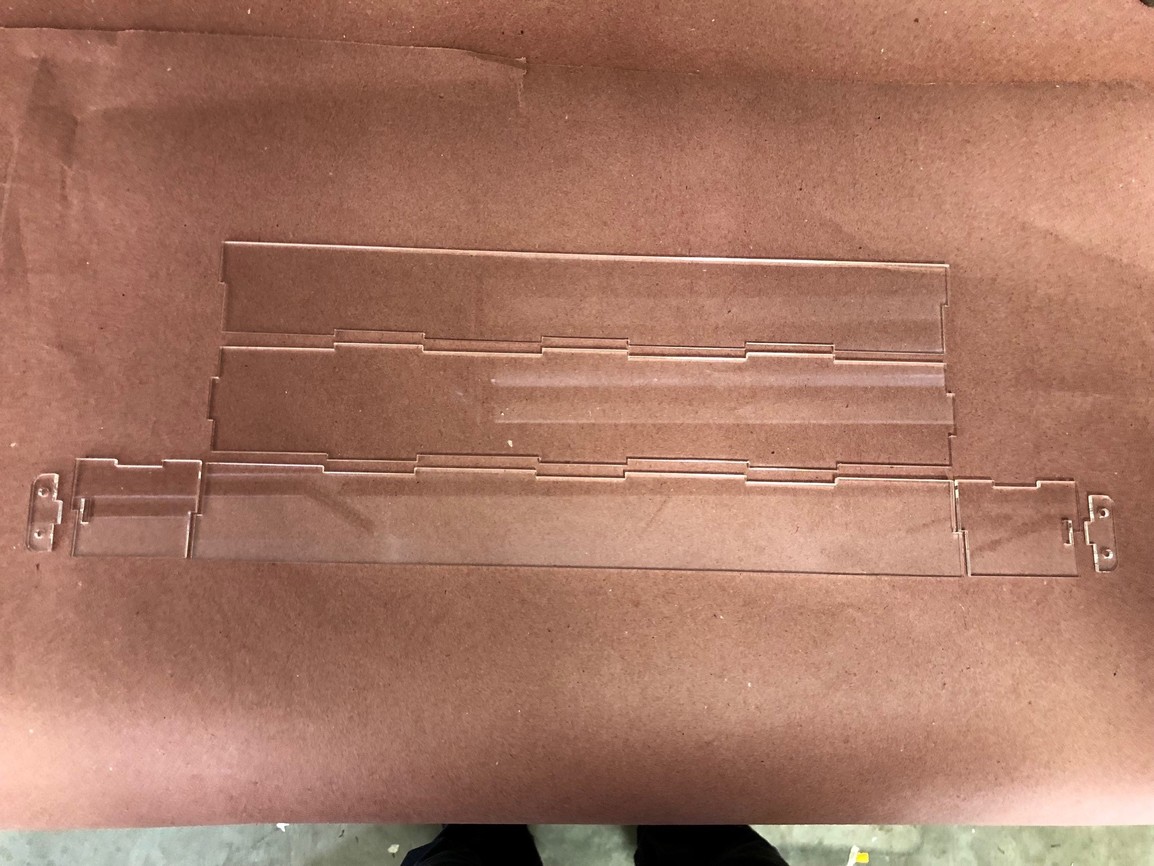
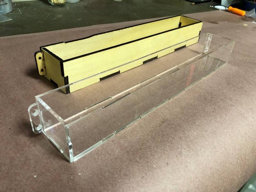
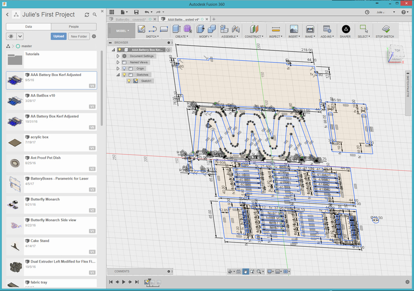
I am making some simple spice racks to be mounted inside my cabinet doors. The parts have a lot of interlocking tabs and slots. To get my learn on, I designed it in Fusion 360 using parameters. I didn’t enter a single dimension onto the parts directly.
I thought I had dialed in the power/speed settings for the acrylic I am using, but some parts were not separating completely. Sometimes it would cut the acrylic but not the back protective sheet. So I slowed down the laser down. But that made the kerf a little bigger and the fit a little sloppier.
SIDETRACK #1 :Dialing in the settings
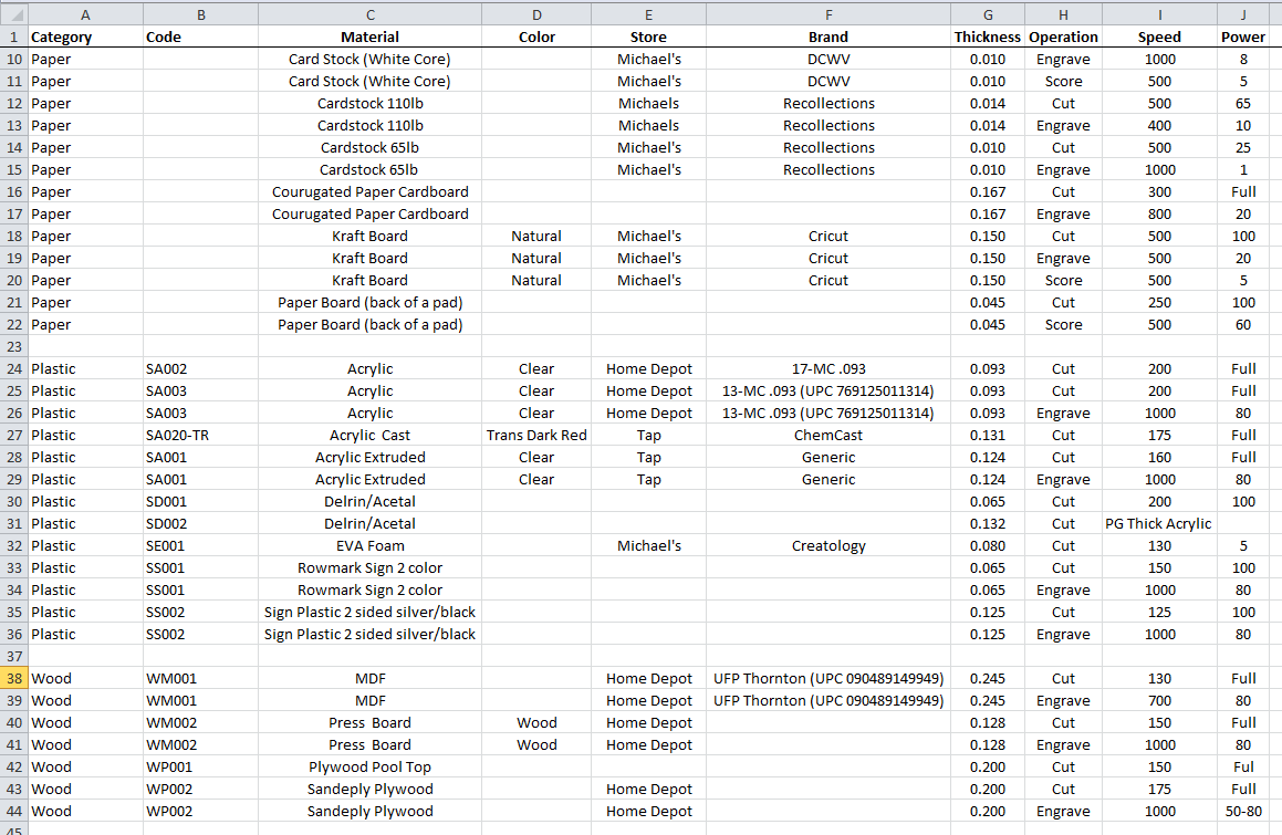
I have a couple test fit gauges for some materials to see how different kerfs work. Time to get serious! I took my setting spreadsheet and added a “code” column. I would give each material its own unique code to engrave onto the test fit gauge.
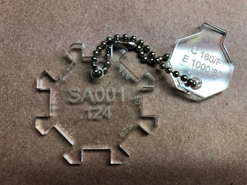
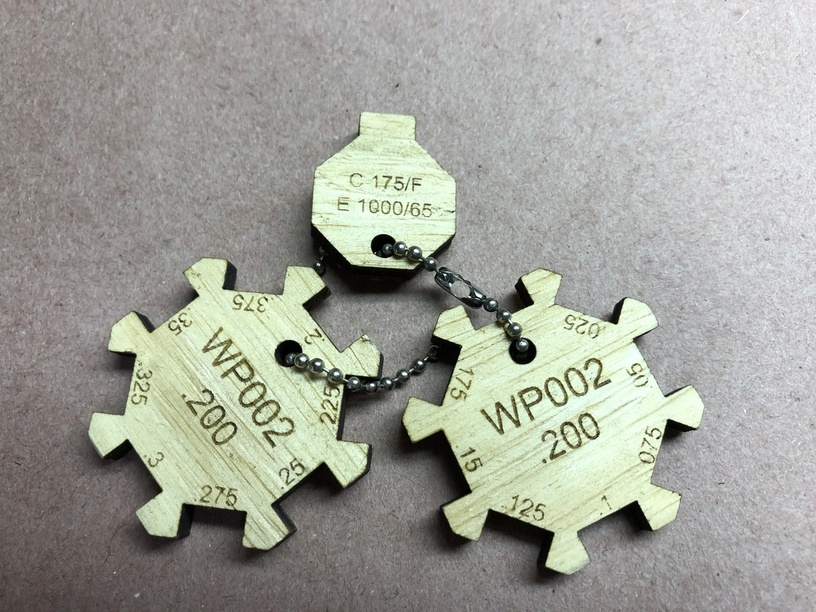
I am working with SA001. (S=Synthetic. A=Acrylic. ) which after some tests I found cuts best at 160/Full. I then made a Test Fit Octagon. Part one is a tab that is 10mm wide with power/speed settings printed on it . Part two is eight sided with slots cut into it, progressively smaller, .05 mm at a time. Each slot is printed with the kerf size; .025 mm bigger each slot. The code and thickness are also printed on it. They are connected together with a little chain.
That showed me that a good acrylic bond would be had with a .15 mm kerf. This rig also demonstrates how the cut isn’t perfectly 90 degrees. If you find a tight fit in one slot then flip the tab over it fits differently. For something super precise that might be important.
SIDETRACK #2:Will my parametric design work in a different material?
I made a second Test Fit Octagon™ out of Home Depot plywood. A tight fit kerf exceeded the original gauge so I made a second one.
BACK ON TRACK:Getting Back to Making Spice Racks
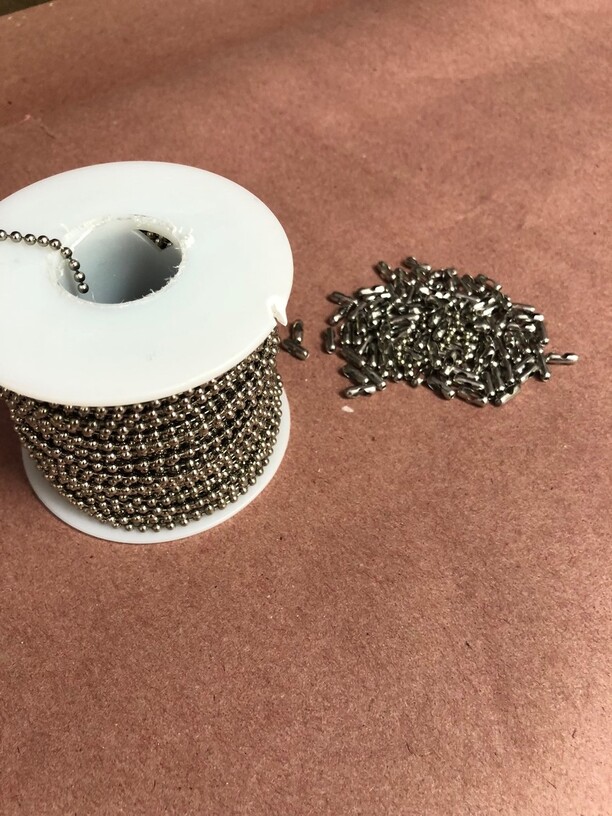
I am getting back to cutting some tight spice racks but I leave you with this tidbit. 100 ft of chain and a fist full of connectors can be found at www.ballchain.com for $25 (not a sponsor of this post)
First, great experiments and writeup, The cut not being a perfect 90 is a known thing with all lasers due to focus. For most wood layups it is not even a thing. For a hard plastic like acrylic yes, it could factor in.
That’s incredibly helpful and exciting to see how you think through your experimenting. Thanks for sharing. Kerf handling and Fusion 360 are on my next big climb.
I’m totally wishing you luck on this one. I know it can be done. Most anything can be done in F360 if you are willing to figure it out and perhaps write some code for the really hard things.
If you get it please once you can repeat it write it up and one of the gatekeepers will put it in the matrix. And I will study it and become a better F360 user. ( I am generally happy to turn my sketches black {fully defined} and have my parameters not explode my model!).
There has been interest in my spreadsheet. It is a work in progress but anybody who would like to take a gander please have fun with it.Power-Speed Settings.xlsx (15.0 KB)
I was trying to figure out how to parameterize the number of tabs on the para boxes I shared here in the free laser designs section and didn’t have luck then.
I think the trick around it though, is not to make the tabs part of a sketch. I havent experimented with this yet but I think that modeling additional boxes as the tabs is the way to go. This way you draw one box, use parameters for its size, then duplicate that box using a rectangular pattern, which can also be parameterized based on number of tabs and the overall size of the whole box.
I like the concept but wouldn’t you have to make a formula where the boxes would grow until X and then +1 box and repeat? Just trying to wrap my head around this…
I’m working on a tutorial that outlines the most consistent way that I have learned to build these tabs. Essentially, you use a secondary sketch on the face where you want them, but you don’t need to sketch out all of the tabs–in fact, if you try to use sketches to control all of your tabs, you can run into situations where the tabs break if you change material size, thickness, tab width, etc. I hope to post something tomorrow to have a few folks review and provide feedback; since I have not done a YouTube tutorial before.
I’d be interested in seeing what you guys come up with too. The first one that I fully parameterized and kerf adjusted had 289 interdependent formulas in it.
Took a while. (But it did work perfectly. After about three weeks of fiddling.)
I’ve really found that trying to kerf adjust in the sketch makes for too many complications. I use the CAM module to make it significantly easier. I’ll add that to the video I’m working on.
Now that I’ve packed up my GF to ship back, I’ll have to keep myself occupied until my replacement arrives.