Sure. I will make a little walkthrough when I’m not at work. I did this in Autodesk Maya, but I’m sure I can come up with a way to do it in software that is available for free.
4 Likes
You are so right. I’m using a jackhammer to do a root canal. I’m still a flatlander when it comes to design and have some familiarity with Inkscape so that’s how I am proceeding. I do need to graduate to a 3D design program but just haven’t given it the time. Another reason to work with OnShape or Fusion 360.
3 Likes
I am hacking something together in openscad that should make for a nice parametric basket weave, but it is not yet pretty. And I am not sure about the best way to convert it to a depth map. (If depths are integer, not-pretty might work fine, otherwise some kind of blend will be required.)
7 Likes
I kind of have to disagree with you on this point. While it is nice to have a 3d representation here, ultimately if you are going to be stuck using a top down perspective and not planning on changing that view, doing it in illustrator, or even photoshop can potentially be faster, and allow you to change the gradient output relatively quickly without having to modify a 3d shape again. And being that depth maps are relative, and dont correlate exactly to real world results in the case of a laser cutter, there is really not much of an advantage that I can see of doing it one way over the other, except for time concerns. Usually that is going to rely on the users experience.
Also, as all of the tools can be used parametrically to provide single changes that propagate throughout all instances of that object, theres not really an advantage in that area either.
I think the opposite might actually be the case here.
However, if you were doing a more complicated model, like a car or human being, a 3d modeling software might be the easier approach. For basketweave, I think illustrator is great.
12 Likes
Perhaps I just need to learn how to do it all more efficiently in Inkscape with tiling, align and distribute once I get the basic shape done. I appreciate your perspective and it gives me hope. Thanks.
2 Likes
The depth map should be at least 16-bit float data so that you can adjust the gradients in an image editor without getting crushed values or banding. That way you can tweak how deep-shallow the relief engraving will be without needing to adjust your model.
Takitus is right that this type of depth map uses relative values. One could easily be generated using absolute values, but having not had the opportunity to play with a laser cutter/engraver yet I just assumed that it would be difficult to predict how the gradient values would translate to actual depth in the engrave anyway since it all depends on your material and power/speed settings. I figured an image that was as close to going from full-white to full-black would give you the most flexibility in playing with the engrave depth by adjusting the laser settings instead of the image.
3 Likes
In the simple top down infinitely tiled case, the 3D work seems like overkill.
But, if you want to do something complex around the edges, or if you want to be able to distort the geometry without causing banding and artifacts in the shading, the 3D approach might have advantages.
6 Likes
I would stick to vector or image editing software if the only intent was a top-down depth map of a simple pattern like this. It’s just much faster… although that’s my perspective of being a 3D modeler for 20+ years and already having intuition of how a depth map drawn in 2D will look when brought into 3D.
@marmak3261 If you use the clone command in Inkscape instead of duplicate, your copies will be linked to the original item so if you resize it or change the gradient appearance, all the copies will update automatically. This makes it pretty quick to set up.
10 Likes
I think you all know that I would use a basket, an aquarium, and a gallon of wine.
No brainer, really. 
John
6 Likes
The thing about using an image editor instead of a 3D program of some kind is that the curve of the basketweave is going to depend on whatever is built into the image program’s idea of a “nice” curved gradient. Which may or may not be right for the 3D shape you want. So you kinda have to choose.
Ultimately I don’t know how finely the GF’s laser power can be controlled; that would determine the number of steps in your gradient, and might save you some computation.
2 Likes
AI has adjustable gradients, and I imagine Inkscape does too. It’s true that the default gradient is probably not gonna be right.
3 Likes
For people without 3D software, nor an inclination to put in the time to become proficient enough with 3D in order to produce a “perfect” depth map, designing it in 2D software with gradient mesh objects is a workable solution.
6 Likes
Agree. Parametric 3D is so powerful. Did a week of classes for Autodesk Inventor a few years back. Amazed me. Model anything, and nondestructive testing, apply a chosen load to a model and know where the weak points are, and when they will fail - all before touching tool or material.
Can’t say I was proficient, but it got to where my eye would land on an object, and I wanted to model it… for fun.
I just wish my ‘Space Navigator’ was supported in Fusion.
6 Likes
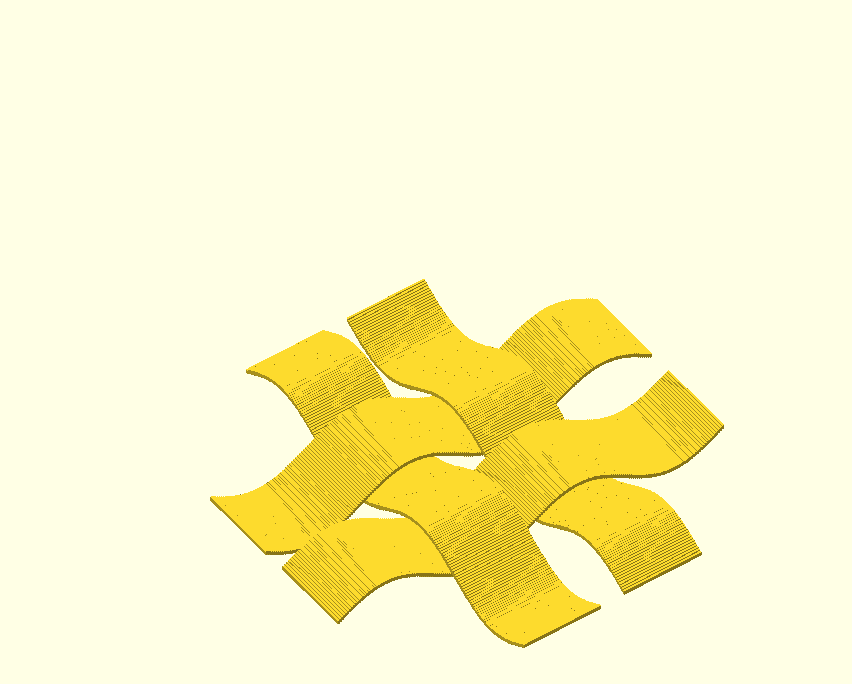
I just had go at making a weave sort of pattern in Onshape. There’s probably better ways to model it then how I did it, but the goal was achieved, so I can work on the modeling aspect more another day. 
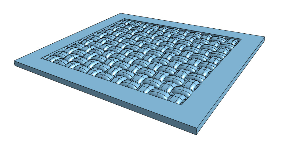
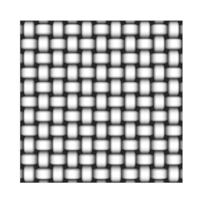
After exporting the model as an .STL (medium resolution) file I used this guide and MeshLab to make a grey scale depth map. I also used Photoshop to Level the image a tiny bit so lightest areas became true white. Looks like it should work.
http://bucketomac.de/stereogram/howto-create-depth-maps/
Looking forward to when I can actually run it on my Glowforge!
Onshape file is here for anyone interested. It will be fun to experiment with making some other types of weave patterns and Celtic designs too.
https://cad.onshape.com/documents/94980a44657c067a19d62f1c/w/59a170b24213885c30018b80/e/c7299fc68071dd86964c7a96
38 Likes
Wow. You don’t post much but it’s a good one when you do. Really amazing to see all the ways to get this done.
11 Likes
Looks like a winner. Can hardly wait to experiment!
4 Likes
I live and breathe Solidworks and was looking for a way to convert a solid model to greyscale. Awesome!
I wish Glowforge would take the “real” 3d data and use it to cut the part (in multiple passes if necessary).
7 Likes
You’d still need to define a 2d projection, so there’s another step regardless.
6 Likes
True @dan. I could see the Glowforge software defaulting to using the Z axis and then we could just make sure our 3D model was rotated the correct way in the modeling software before exporting and feeding it to the forge software.
If the resulting gray scale image was always clamped 0-1 based on the closest and furthest depth points in the 3D model (in the 2D projection direction) then something like Photoshop’s Levels tool in the forge’s UI would be the only other thing needed I think.
3 Likes
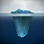
Well that’s the kicker right there. A lot of times you really wouldn’t want that in your depth maps. Sometimes you only want the “tip of the iceberg” per se. Using the full depth of an object could leave you with almost nothing to see if the vast majority of it is occluded by itself in that perspective.
10 Likes