@takitus, I don’t understanding what you mean by “if the vast majority of it is occluded by itself in that perspective.” Can you explain a bit more or do you have an example so I could understand?
I do recognize that if a 3D model had an extreme “height” difference for a desired perspective that the gray scale output might not have as nice a gradation at the depth you care about. A manual Z min/max adjustment option could be useful there in addition to a Levels (or Curves) sort of interface.
Well I was actually using the iceberg as an example. I will expand upon that a bit.
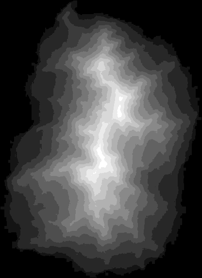
If you look at that iceberg from top down, the widest part is just at the very top, right about where the water line is. Lets say 5% would be visible from a top down view. That means if the heightmap was generated from this view, to the full extent of the object, you would really only see the very very top. That means the heightmap you were looking at would come out like this:
Ultimately it would be a loss of a lot of information that you cant see anyways. So a common practice when dealing with height maps is that you only set the lower height line at the last part you can see before occlusion (e.g. when looking at someones face straight on, you cant see past the ears, so you generally set the lower boundary right about there).
yeah exactly. You would definitely want to set the range to include in that depth map. if I normalize (using levels in photoshop) the depth map from the previous example it only leaves you with about 12 different distinguished height:
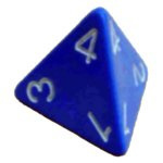
And the iceberg has an obvious right side up - if you imagine the thing rotated 10 degrees, then it becomes really complicated. Think about a shape like this floating in space, where e.g. the top surface is flat - using this approach would just give you a triangle.
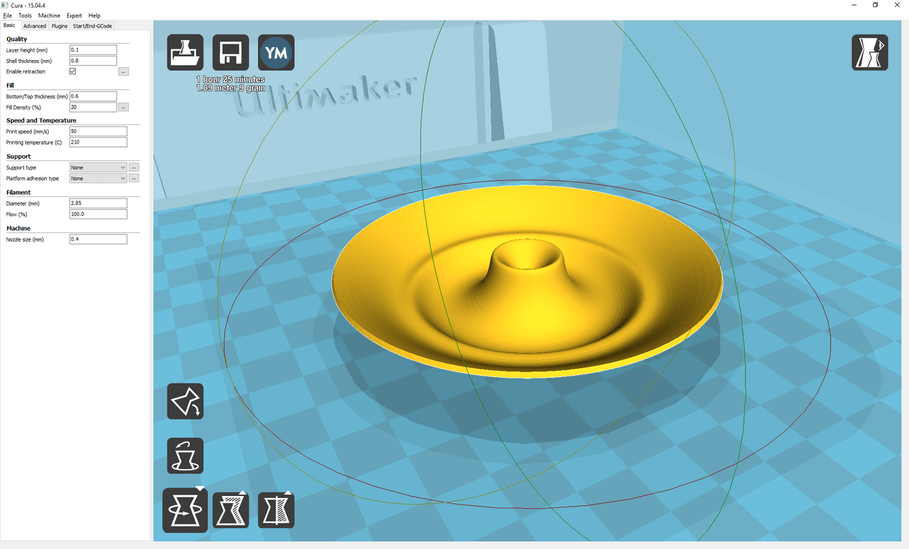
I agree with @Dan that you need to define what direction is the x,y,z direction for .STL file (see CURA or other 3d printer software). It has simple controls to flip/rotate/scale, etc the part so that it is oriented into the proper orientation for FDM fabrication which could be used in the Glowforge interface to drop the model in the correct x,y position as from the camera’s perspective.
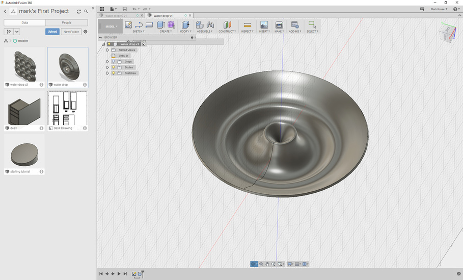
.STEP are native 3d files have more native x,y,z data already embedded into the part and aren’t meshed the same way as STL files are.
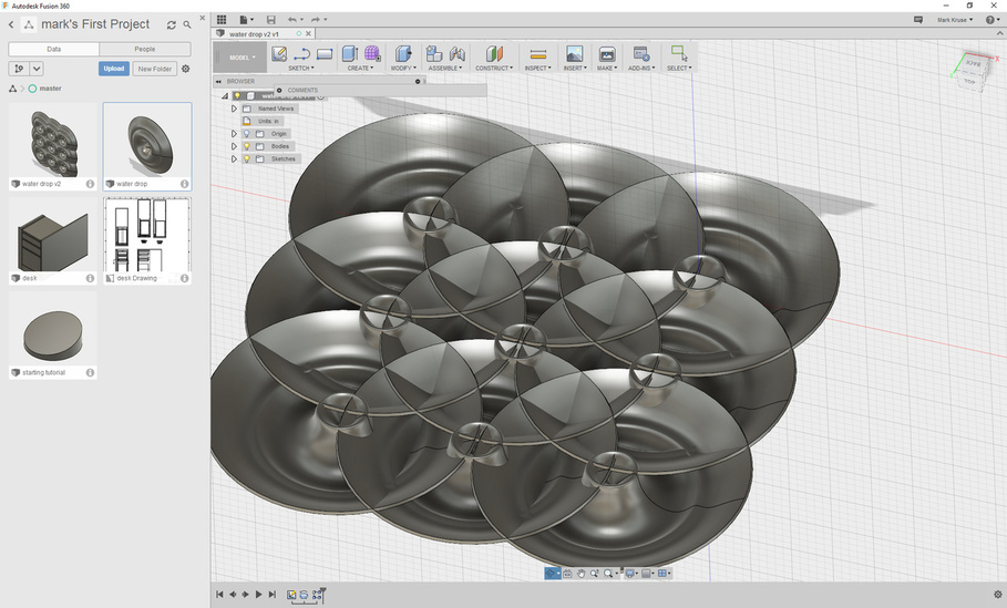
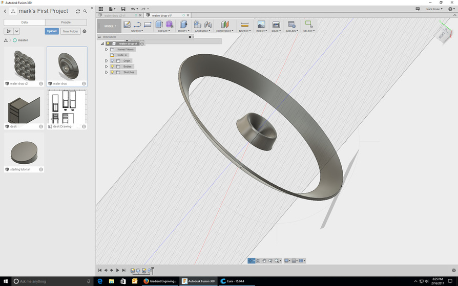
Taking a simple water droplet spline and making an array can give you a complex surface to cut into a laser part that is visually interesting.
To Dan’s point, I don’t care what is on the underside of the “iceburg” because I’m not looking “through” the part to see what is grey-scaled under the surface. I only want to re-create what is visible from the positive z axis that is visible. I was imagining 1 of the 2 scenarios to use the laser cutter to make this pattern:
The software would assume (or user input) a max depth that the laser could engrave in one/multiple passes. So if the depth of the model is 10", and you can only cut 1/8" into wood, the cut would be scaled to the depth of cut and be prepared for engraving using that scale.
The software would take the depth of cut literally. Scan one of cutting the engrave would cut the first 1/8", the second scan would take the next 1/8", and so on until max focal length is used up.
Depending on the size of the autofocus beam, it could feed back the “actual” depth cut into the part similar to how Markforged is using a laser to measure for part accuracy.
Look at line 74 above from marmil. He had an excellent post that described a way to produce a greyscale from STL.
I’m going a step further and proposing kicking this antiquated idea that everyone needs to make 4 extra steps exporting between 3 programs, smoothing and fiddling with the greyscale 256 bit blah blah blah garbage to the curb and cut straight off 3d model.
It would be nice if the Glowforge could do absolutely everything. I think the question of “what can we expect it to do?” needs to be asked though.
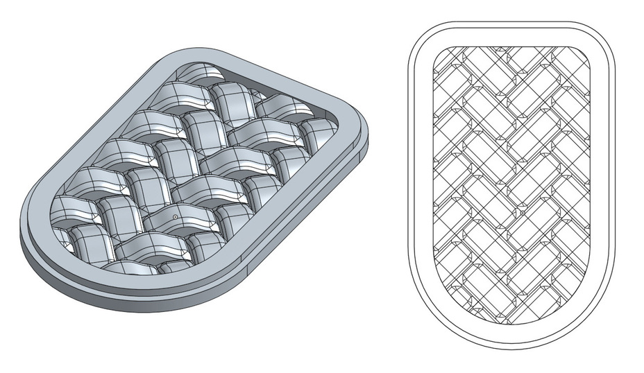
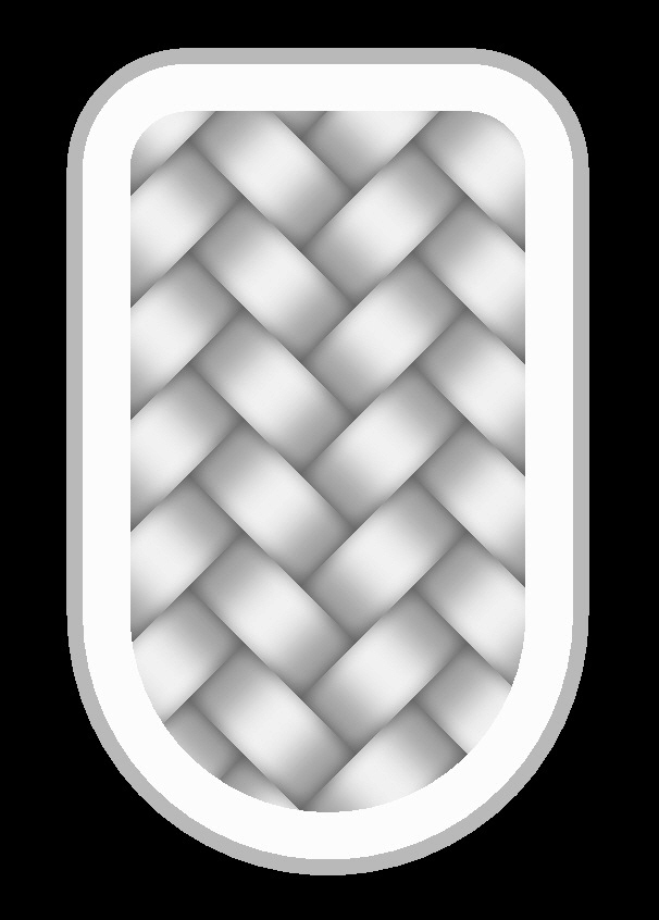
OK, they could make it so it can load STLs, great. But what if the STL is in the wrong orientation? Now they have to make it so the UI has controls for rotating the model. Scaling the model is just a given. But what about models that occlude themselves and we’re only interested in the parts that are visible? No prob, just make it so we can select the top and bottom range and we’re all set. How about models that include things we don’t want in our engrave (eg. remove the body if we only want to engrave a character’s head)? Let’s ask them to add some way to exclude those parts of the model. Next we might want to add some simple primitives to “jazz-up” our engraves, that’s not asking too much, is it? And what about adding a bump map to the model for some extra realism? That basket-weave pattern would look even better with some authentic wood or leather grain on it.
…
The list of potential features is endless.
edit…
Oops, although I wrote something like this a few times, I guess I had deleted it by the time I actually clicked Reply.
I’d prefer the Glowforge software to be focused on running the Glowforge hardware. The rest of the stuff can be handled by other software, programs written with a focus on doing the rest of the stuff.
Aww come on, I’m more than happy with my current workflow… Geomagic Design to build a quick hard edge model, import into ZBrush to fine tune and sculpt details before exporting a depth map. Use GIMP to tweak the depth map, adjusting levels, knocking out the bitmap background, make it into an image that can tile seamlessly if needed. Finally using Inkscape to build the final artwork layout that can be imported into the GF software…
Nice rant. Glad you got it off your chest. They checked off the box on greyscale. Proven, done capable. Maybe not perfect, but getting there.
Does the machine have accurate depth capabilities with proofgrade material? Supposedly yes.
Does the machine have on-head depth mapping? Yes
This thread is discussing the multiple ways that someone has to manipulate a file to do something that should be possible by specifying exact depth information from a drawing.
Open source fdm programs from every Tom, Dick and Harry already the ability to process, flip, rotate stl files, so it’s not exactly out of the realm of possibilities to process it in an easy to use interface. In case you hadn’t noticed, these forums are rife with speculation on future capability.
I want what you draw to be what you get. Not fuzzy greyscale hopes and dreams that you got it dark enough to engrave the depth you expect in proofgrade material.
“Other programs” as you suggest won’t do that. Glowforge team would have to own up to the marketing hype of the “worlds first 3D laser printer” a reality.
Who knows, maybe “turn the Glowforge software into a full-blown 3D editing suite because other software does it too” is a hopper item they just haven’t revealed yet. I’ve got my fingers crossed for you. NO… for US!
Sorry for any confusion - the answer here is “it depends on material”. We’ve taken the rather gothic approach of fabricating some of our Proofgrade material from the corpses of once-living plants, which leads to some predictable variations in the resulting product.
Or put another way, the depth accuracy will vary between materials like hardwood (poor) to acrylic (good).
I noticed that by default MeshLab uses a FOV of 60 deg. To get an orthographic view I learned that Shift-mousewheel can change the FOV, and if it’s rolled toward zero it will change to an orthographic view when FOV gets down to 5 deg or less. This helps eliminate a bit of distortion in some cases so I would recommend trying it if using MeshLab to create a depth map.