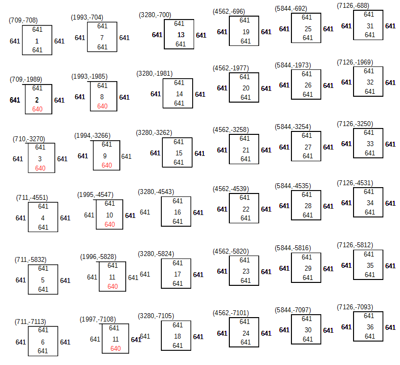
This is what I found when I told it to score 36 unit squares on a regular grid each a different colour and focus height. These are the coordinates in motor steps of the top left corner of each square and the side lengths. The number in the middle is the order they were done. I.e. down the columns.
This isn’t to scale but it has some very odd distortions. Most sides are 641 steps but the bottom of 7 squares are 640 so they don’t meet at the first corner and everything following that is one step to the left.
Each column starts 4 steps higher than the last. The pitch between columns is 1280 but the pitch between rows is 1281.
This is the original svg file and you can see it is perfectly regular
<?xml version="1.0" ?>
<svg baseProfile="full" height="600px" version="1.1" viewBox="-1.1055 -1.1055 13.211 13.211" width="600px" xmlns="http://www.w3.org/2000/svg" xmlns:ev="http://www.w3.org/2001/xml-events" xmlns:xlink="
http://www.w3.org/1999/xlink">
        <defs/>
        <path d="M 0.0,0.0 L 1.0,0.0 L 1.0,1.0 L 0.0,1.0 L 0.0,0.0" fill="none" stroke="rgb(100, 100, 0)" stroke-width="0.011"/>
        <path d="M 0.0,2.0 L 1.0,2.0 L 1.0,3.0 L 0.0,3.0 L 0.0,2.0" fill="none" stroke="rgb(100, 101, 0)" stroke-width="0.011"/>
        <path d="M 0.0,4.0 L 1.0,4.0 L 1.0,5.0 L 0.0,5.0 L 0.0,4.0" fill="none" stroke="rgb(100, 102, 0)" stroke-width="0.011"/>
        <path d="M 0.0,6.0 L 1.0,6.0 L 1.0,7.0 L 0.0,7.0 L 0.0,6.0" fill="none" stroke="rgb(100, 103, 0)" stroke-width="0.011"/>
        <path d="M 0.0,8.0 L 1.0,8.0 L 1.0,9.0 L 0.0,9.0 L 0.0,8.0" fill="none" stroke="rgb(100, 104, 0)" stroke-width="0.011"/>
        <path d="M 0.0,10.0 L 1.0,10.0 L 1.0,11.0 L 0.0,11.0 L 0.0,10.0" fill="none" stroke="rgb(100, 105, 0)" stroke-width="0.011"/>
        <path d="M 2.0,0.0 L 3.0,0.0 L 3.0,1.0 L 2.0,1.0 L 2.0,0.0" fill="none" stroke="rgb(101, 100, 0)" stroke-width="0.011"/>
        <path d="M 2.0,2.0 L 3.0,2.0 L 3.0,3.0 L 2.0,3.0 L 2.0,2.0" fill="none" stroke="rgb(101, 101, 0)" stroke-width="0.011"/>
        <path d="M 2.0,4.0 L 3.0,4.0 L 3.0,5.0 L 2.0,5.0 L 2.0,4.0" fill="none" stroke="rgb(101, 102, 0)" stroke-width="0.011"/>
        <path d="M 2.0,6.0 L 3.0,6.0 L 3.0,7.0 L 2.0,7.0 L 2.0,6.0" fill="none" stroke="rgb(101, 103, 0)" stroke-width="0.011"/>
        <path d="M 2.0,8.0 L 3.0,8.0 L 3.0,9.0 L 2.0,9.0 L 2.0,8.0" fill="none" stroke="rgb(101, 104, 0)" stroke-width="0.011"/>
        <path d="M 2.0,10.0 L 3.0,10.0 L 3.0,11.0 L 2.0,11.0 L 2.0,10.0" fill="none" stroke="rgb(101, 105, 0)" stroke-width="0.011"/>
        <path d="M 4.0,0.0 L 5.0,0.0 L 5.0,1.0 L 4.0,1.0 L 4.0,0.0" fill="none" stroke="rgb(102, 100, 0)" stroke-width="0.011"/>
        <path d="M 4.0,2.0 L 5.0,2.0 L 5.0,3.0 L 4.0,3.0 L 4.0,2.0" fill="none" stroke="rgb(102, 101, 0)" stroke-width="0.011"/>
        <path d="M 4.0,4.0 L 5.0,4.0 L 5.0,5.0 L 4.0,5.0 L 4.0,4.0" fill="none" stroke="rgb(102, 102, 0)" stroke-width="0.011"/>
        <path d="M 4.0,6.0 L 5.0,6.0 L 5.0,7.0 L 4.0,7.0 L 4.0,6.0" fill="none" stroke="rgb(102, 103, 0)" stroke-width="0.011"/>
        <path d="M 4.0,8.0 L 5.0,8.0 L 5.0,9.0 L 4.0,9.0 L 4.0,8.0" fill="none" stroke="rgb(102, 104, 0)" stroke-width="0.011"/>
        <path d="M 4.0,10.0 L 5.0,10.0 L 5.0,11.0 L 4.0,11.0 L 4.0,10.0" fill="none" stroke="rgb(102, 105, 0)" stroke-width="0.011"/>
        <path d="M 6.0,0.0 L 7.0,0.0 L 7.0,1.0 L 6.0,1.0 L 6.0,0.0" fill="none" stroke="rgb(103, 100, 0)" stroke-width="0.011"/>
        <path d="M 6.0,2.0 L 7.0,2.0 L 7.0,3.0 L 6.0,3.0 L 6.0,2.0" fill="none" stroke="rgb(103, 101, 0)" stroke-width="0.011"/>
        <path d="M 6.0,4.0 L 7.0,4.0 L 7.0,5.0 L 6.0,5.0 L 6.0,4.0" fill="none" stroke="rgb(103, 102, 0)" stroke-width="0.011"/>
        <path d="M 6.0,6.0 L 7.0,6.0 L 7.0,7.0 L 6.0,7.0 L 6.0,6.0" fill="none" stroke="rgb(103, 103, 0)" stroke-width="0.011"/>
        <path d="M 6.0,8.0 L 7.0,8.0 L 7.0,9.0 L 6.0,9.0 L 6.0,8.0" fill="none" stroke="rgb(103, 104, 0)" stroke-width="0.011"/>
        <path d="M 6.0,10.0 L 7.0,10.0 L 7.0,11.0 L 6.0,11.0 L 6.0,10.0" fill="none" stroke="rgb(103, 105, 0)" stroke-width="0.011"/>
        <path d="M 8.0,0.0 L 9.0,0.0 L 9.0,1.0 L 8.0,1.0 L 8.0,0.0" fill="none" stroke="rgb(104, 100, 0)" stroke-width="0.011"/>
        <path d="M 8.0,2.0 L 9.0,2.0 L 9.0,3.0 L 8.0,3.0 L 8.0,2.0" fill="none" stroke="rgb(104, 101, 0)" stroke-width="0.011"/>
        <path d="M 8.0,4.0 L 9.0,4.0 L 9.0,5.0 L 8.0,5.0 L 8.0,4.0" fill="none" stroke="rgb(104, 102, 0)" stroke-width="0.011"/>
        <path d="M 8.0,6.0 L 9.0,6.0 L 9.0,7.0 L 8.0,7.0 L 8.0,6.0" fill="none" stroke="rgb(104, 103, 0)" stroke-width="0.011"/>
        <path d="M 8.0,8.0 L 9.0,8.0 L 9.0,9.0 L 8.0,9.0 L 8.0,8.0" fill="none" stroke="rgb(104, 104, 0)" stroke-width="0.011"/>
        <path d="M 8.0,10.0 L 9.0,10.0 L 9.0,11.0 L 8.0,11.0 L 8.0,10.0" fill="none" stroke="rgb(104, 105, 0)" stroke-width="0.011"/>
        <path d="M 10.0,0.0 L 11.0,0.0 L 11.0,1.0 L 10.0,1.0 L 10.0,0.0" fill="none" stroke="rgb(105, 100, 0)" stroke-width="0.011"/>
        <path d="M 10.0,2.0 L 11.0,2.0 L 11.0,3.0 L 10.0,3.0 L 10.0,2.0" fill="none" stroke="rgb(105, 101, 0)" stroke-width="0.011"/>
        <path d="M 10.0,4.0 L 11.0,4.0 L 11.0,5.0 L 10.0,5.0 L 10.0,4.0" fill="none" stroke="rgb(105, 102, 0)" stroke-width="0.011"/>
        <path d="M 10.0,6.0 L 11.0,6.0 L 11.0,7.0 L 10.0,7.0 L 10.0,6.0" fill="none" stroke="rgb(105, 103, 0)" stroke-width="0.011"/>
        <path d="M 10.0,8.0 L 11.0,8.0 L 11.0,9.0 L 10.0,9.0 L 10.0,8.0" fill="none" stroke="rgb(105, 104, 0)" stroke-width="0.011"/>
        <path d="M 10.0,10.0 L 11.0,10.0 L 11.0,11.0 L 10.0,11.0 L 10.0,10.0" fill="none" stroke="rgb(105, 105, 0)" stroke-width="0.011"/>
</svg>
I have no idea how or why it would produce skewed results like this. Yes conversion to motor steps could produce off by one errors but the last coordinate of each path is the same as the first so should always convert to the same motor position.
If Y was skewed, say to compensate for a skewed gantry then the squares should be rhombuses. Having them still squares on a skewed grid makes no sense to me.