My camera is soooo far off it serves no real purpose for me within the APP. I notice that it seems to be used to “center” the Glowforge on startup, but I see no purpose for it while running.
I therefore would like to propose the following:
Within the APP - under the GEAR ICON drop menu:
Add a new toggle here called “Camera View - Grid View”
If the Grid View is selected do not load the bed image
instead, load a grid that has X-Y coordinates.
Allow users to type in X/Y coordinates to POSITION graphics or images.
another benefit of this is less load time and fewer resources being used within the browser as we could dump off the 500kb image and the processing used to render it and “adjust” it thus simplifying the software. The JavaScript needed to add in X-Y cords should be very lightweight, several libraries under 100kb are out there that should fit within the GUI that GF uses in the APP.
A good example of X-Y cords functionality is easily seen in many CnC programs (Xcarve, Autodesk, Solidcam) and even Vector Software such as Adobe Illustrator.
Thank you for your consideration.
PS: if this is already an idea somewhere her let me know so I can “vote it up” or support it.
Thanks Christian! Got it. Also FYI, Problems & Support is the best place to post feature requests to ensure they get seen by the right people (although I caught this one).
There is already a series of numbers on the top and left side that you can scale and position your work. That will make your design scaled to two inches be an actual two inches but the location of 0-0 on the bed will still not be more accurate, as you can already see the location in the camera but getting the fish-eye camera to an orthogonal correction is still a very tricky thing that I have seen improve with time used but every machine and camera is apparently a bit different.
Here is why I feel the Camera should just be “turned off” if a user wants it off. (I am aware of several posts on this topic and I did not like how they were resolved). I am under the impression that its this way for most people who have the founder models? I feel like this is not a big enough problem for me to deal with or ask for any kind of return or exchange.
@rbtdanforth
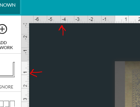
Are you talking about the “screen rulers”?
I feel like those are a nice “general guide” as they go down to an of 1/8th inch. …
How can I use those to “scale and position my work” other than dragging or nudging using the arrow keys? (a nice feature but tedious, unreliable, and inaccurate)
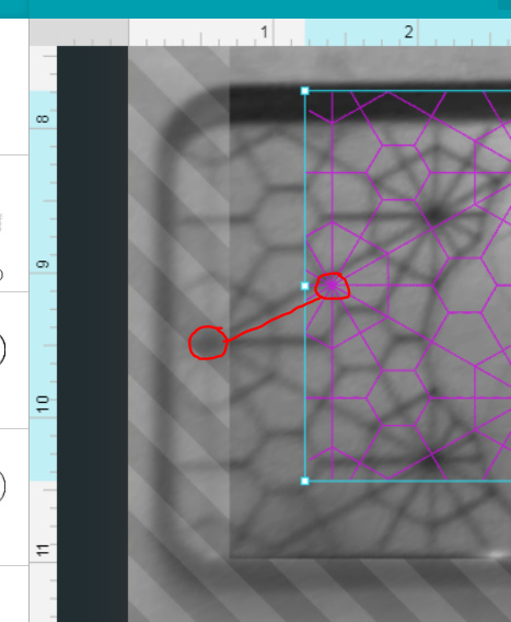
The ability to type in something like “X=32.17 - Y:144.92” and have artwork move to that position is what I feel is a more appropriate solution. The only way I am able to solve absolute positioning issues is to include an “empty square” that is the exact size of the bed, then delete that item.
Yes. When I first started they were not there at all, and I was totally not knowing how big my work would cut to except what it was in Inkscape but scaled after was a leap.
You could make a cut in a larger piece of exactly the cut-able area and have a means of measuring it but you may find the results a hair different with each reset but quite different after several cuts. Especially after many sharp turns.
Of course the height of the work needs to match the GFUI height or nothing will line up. I bought the micrometer that gets an extra decimal when measuring and that can make a difference too.
Thank you for your suggestions, I appreciate your willingness to reach out.
I use very similar tactics to line up my artwork, a Mitutoyo Calliper is critical and I have even uploaded my own “grid” graphic (and set it to ignore)… alas, such analog methods pale in comparison to being able to type in coordinates.
To elaborate, all my efforts to date have been based on “not needing the bed image” because of its inaccuracy. As such, I have no use for it, (which is technically a GOOD thing)
My purpose here for this post is as follows:
1- submit an idea (bed image is moot)
2- point out a way to improve the software (coordinates)
A:: making it more accurate and professional
B:: literally consume less processing power (important for web apps)
Might you agree that this feature would be an improvement over the existing tools we have?
Understanding what exists is needed to understand the rest, the first is that there is no actual zero,zero on the crumb tray, There is in many other systems but not this one. Snapmarks are a means of relating the GFUI to the crumb tray, but not ready for prime time. Until then the camera is the method and as it is a fish eye camera, turning that image to a flat image is a challenge, Things have improved a lot but best I can tell, every machine is slightly different and needs to hone in a bit by doing,
There is perhaps a dozen threads that folk used to other machines have wanted a real location on the crumb tray, and Dan among others have given their reasons why they went as they did, Directly under the camera has the least distortion but it hardly uses up the cuttable area,
I like the idea of reading several decimal points but just where that would be could be an issue; the middle of the piece? a corner? whatever corner was chosen it would not be the convenient one much of the time but is the best part of your suggestion as you could use the xy distance that a test score landed and where it needed to land and move the design by that much.
In the end, the key issue is where the design is relative to where it will fall on the bed. In other systems, this is very mechanical in this one it is not so the camera looking at your material IS that system, You have the screen rulers as that grid and I frequently use “Kentucky Windage” in distances below 1/8 of an inch. As you have noted even 1/8 inch error is not uncommon so chasing precision below the error probability is not much use,
As ever the big advantage of cloud programming is that there is constant improvement, and there has been plenty. If it was perfect the first time no improvement could be hoped for.
@rbtdanforth
I am a full stack developer. I code PHP, WP, Magento, eCommerce, I maintain and develop SaSS systems, APPs, paid membership and community sites, ect…
I feel like you are speaking from the perspective of someone who works at GlowForge, is that the case? Are you a Software Developer? If so, This is an AWESOME beta launch from a BOLD company breaking into a “red sea” Laser market and creating a “blue sky” opportunity for a specific demographic that was IMPRESSIVE to watch and be part of. (Thank you for that.)
As such:
here I am as an end user (not a developer, dev hat is off) and I have told you about a feature I need, a feature your competitors have, and a useful one at that. Please consider it.
I appreciate the “personal feeling” that comes with confusing a “feature request” for a “criticism” because I feel it every time I pop open ZenDesk or Mopinion and see 1500 new messages that tell me what is already on my Versioning list… lol (the public loves to say what I already know)
Let me make clear: I am not criticizing this software, I am part of the unlimited source of FREE consulting, Beta Focus testing and eternal well of never-ending end user feedback… that will improve the quality of this Software via the community - but only if the Developers truly appreciate the nature of this symbiotic relationship. (we ask, dev do)
Here is an observation dry and candid, honest. (and also an opinion)
Get rid of the PRO model (All models should have the same hardware)
Convert the Software over to a true SASS - “Fremium” and “Pro” Software
Collect RESIDUAL income on the software (charge $5 per day to use PRO, or $50 per month)
Let “non pro” software users be free, but don’t give them things (like X-Y coordinates)
Make “pro” users pay an upgrade fee to “activate” the pass-through slot
This will simplify manufacturing (1 mold instead of 2)
It will allow better innovation (1 hardware system to improve and innovate)
And, will create multiple revenue streams.
Thank you for those links. I am intimately familiar with these topics, I already use method you suggest here, I also use Draft boards to create JIGs.
I am aware of the ‘snapmarks’ - which are ARBITRARY to the Analog absolute 0,0 vs X,Y. They seem to me to be an elaborate way to avoid using a grid. (I also understand why that happens with software, time, budget, web-standards, ect…)
I am past the “placation” stage (ie: use this ducktape to fix the space ship).
I am now in the “squeaky wheel stage”. (ie: back on earth asking engineers to improve the next spacewalk based on whats happening on the front line)
I am not mad,
just making sure this ‘uservoice’ is added to the public demand for a specific innovation.
To be clear #1- it would be great to TURN OFF the camera.
It is of no use to me (I feel calling it ‘broken’ would be rude, lets say its desired operational accuracy is lacking). I have a digital caliper, I measure 5 times, but sometimes have to cut twice because I have no reliable, intuitive and unchanging GUI positioning system (other than than a graphic I upload from Illustrator and a Board that I cut which shows the max engraving area)
#2- Feature Request.
Lets say I am voting for something that the community has been asking for, I trust my vote is cast here. XY grid - please. willing to pay to have it.
Cheers
PS: I do like this thing, im using it, I want to like it more
I am just a user like yourself from the opposite quarter of the country from the company. I would guess over half (90%?) know more about software than I do, including yourself. But I have the impression that you misunderstood the difference in approach used. I was just trying to point out the logic that did not make sense and try to clear up the situation. the GFUI has the edge scales that act as a grid, but it is the connection to the crumb tray that is at issue. It is not fixed,
If you turned off the camera, you would not be better off. One does not need high-level programming to go there. I at no point saw it as criticism but I have seen folk (including myself) come up with ideas that are not practical once the situation was understood. The issue of wanting a fixed zero point on the GFUI to the cutting surface has been a common one.
The problem I have with using the bed image to place my artwork is that I’m partially colorblind. Sometimes there isn’t enough contrast between the artwork’s outlines and whatever material happens to be in the GF. I have the same problem when trying to distinguish which layer is active because they often look the same to me. Having a grid instead of the bed image would help immensely especially if we are offered the ability to toggle the grid background from light to dark.
Ideally, I think it would be really cool if the GF could project a laser crosshair during material setup. You could specify an origin in the software’s grid display and the GF would show you that location by illuminating the crosshair on your material at the exact coordinates where the laser will cut/engrave. Who knows, maybe GF can sell an upgradeable laser print head in the future that has this feature.