Is my lid camera misaligned?

You are always helpful…

3 Likes

Oh boy, that’s a bit of a mess. Thanks for testing @jamesdhatch

Would we get better results on thicker board to avoid warping? You could just bond the printed sheet to cardboard?

Another (different) test (for anybody who’s willing and does not see it as some unreasonable demand…) is to engrave a simple 10x10mm grid on material the full bed size - no camera involved. I am sure it will engrave dimensionally accurate but there’s a bit of confusion as to accuracy of the GF generally I think.

The rulers are coming out pretty accurately when photographed without parallax, so I think it is probably more accurate that you can measure by eye with a ruler.

I would cut out an L shape and measure the inside leg length with calipers. That gives a kerf independent dimension to measure.

4 Likes

I don’t think so. I was watching the laser operations and it was wrong from the start - the first vertical and horizontals were not lined up with the grid lines on the paper. Those were in the upper left side of the paper. It also showed similar behavior when it got to the lower right. It was a fairly random walk across the paper so it was a fair amount into the project before it started having paper blow or cut out and fly off.

2 Likes

I was running this same test the other day. Ran into some of the same problems, specifically the scanned artwork outside the print area. Another issue I had is I was cutting thicker material previously. I scanned the artwork, then I set the material thickness. This caused the scanned artwork and the picture on the bed to become misaligned. I had to rescan.
I didn’t actually do the engrave, because I had other projects to do and it was longer than I thought it would be, but I’m planning on it later this week.

3 Likes

I did do a 10LPI test. It was… interesting, but I wouldn’t say conclusive.

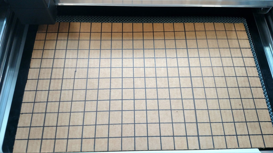
1"grid on cardboard.

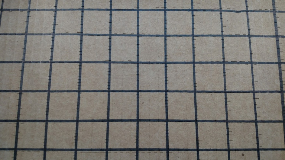
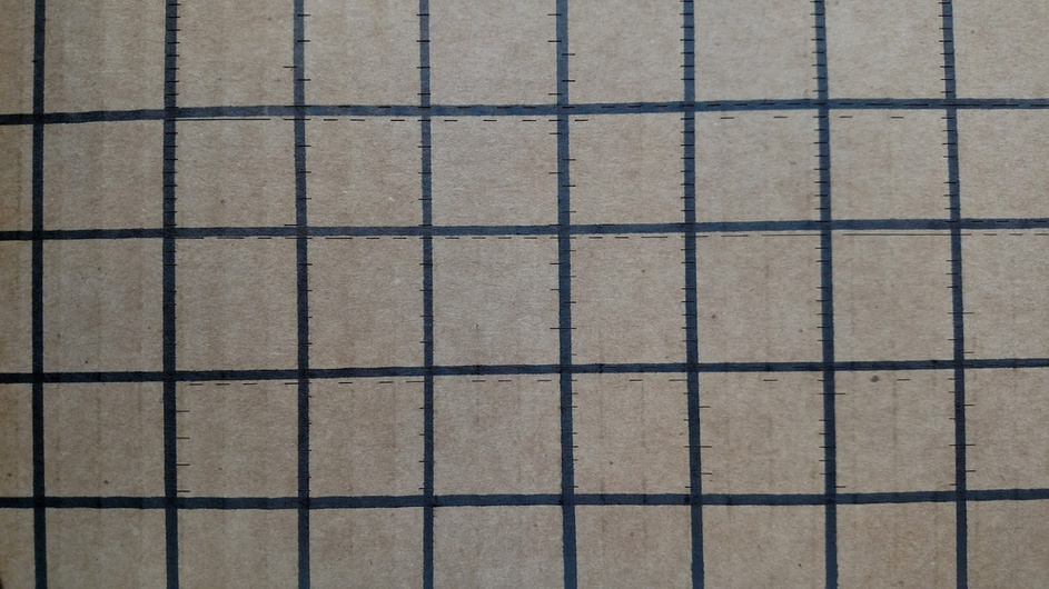
Here is a picture of the engrave lines around the center of the image.
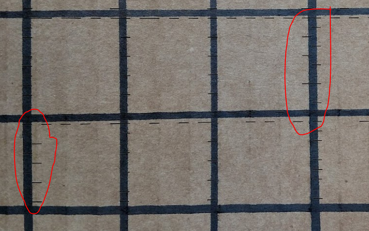
Bottom left.

There is a weird anomaly that happened if a few places. The engrave lines bounced around (see image below). This is significantly wider that what was depicted in the scan. I’m curious if it is caused by the 10LPI setting, which is why I’m going to do this test again.

13 Likes

Note they use the plural of the word “camera.” So while alignment isn’t up to snuff with the lid camera alone, I have high hopes for what they can do with the head camera and some clever programming. I’m pretty confident (from a geometric analysis I did a while back) they will never be able to align satisfactorily with the lid camera alone.

3 Likes

I think the head camera is for edges. I will be surprised if it is used for trace mode.

I can imagine using the head camera to do some spot sampling of the artwork, and comparing the results with the lid camera image. Then based on that, warping the lid camera image locally to match the head camera reality. Like I’ve always said, a monumental programming task!

3 Likes

It looks like at 10 LPI it is sampling the grid on a 0.1" grid so you are getting aliasing. I think the other tests were done with scores, not raster.

3 Likes

Look at screenshots of the Muse’s bed photo stitching and you’ll see why it’s so hard. It depends greatly on the depth of whatever it is you’re trying to capture. With the Muse it looks like they assume a certain depth. Something sloped like a laptop would require what I imagine to be some pretty serious processing to take the depth map from the laser rangefinder, marry that up with the photos from the lid and head camera, remove any lens aberration (fisheye etc.) and then stitch things up accurately.

6 Likes

Thanks @palmercr, looking forward to your results.

To me there is a clear distinction between accuracy of the laser in ‘normal’ operation - i.e. from a vector or raster file and conversely, GF’s attempt at optical alignment via the camera.

I expect the former to be flawless since the hardware seems to be quality but any work involving the camera - either scanning images or aligning materials for cutting or engraving - seems still flawed at this point.

All of this comes back to the requirement for an absolute zero / homing point which has been requested by many. Currently we seem to be resigned to makeshift solutions of rigs & jigs & trial & error. If we’re not able to reliably cut or engrave from a known physical (calibrated) 0,0 point on the bed, this will hugely limit the unit’s functionality for us. And it will be a major design flaw.

5 Likes

Yes without limit switches the cameras need to be very accurate. But they also need be accurate for trace mode, double sided cuts and pass through, not to mention dynamic autofocus. So they are fundamental to the machine.

You are not, so you may want to consider a refund to purchase a system that better meets your needs. I’d hate to lose you as a customer, but I want you to get the system that’s the best fit for your requirements. I’d hate more for it to arrive and you to be surprised or disappointed.

4 Likes

I have been following the lid camera alignment threads a bit, although I am apparently not up to date with all of the results. I have seen a lot of hand drawn grids, and tests against that, but has anyone Vector engraved a grid to test the accuracy of that? It would seem that should be accurate enough to then test against.

I was under the impression that the head camera was eventually going to be enabled for precision alignment. Is this still in the hopper? That would seem to be more important than a true 0,0 alignment, but I’m surprised that is not also going to be an option.

1 Like

Now that is finally put to bed :slight_smile:

If I want to do precision alignment on small pieces, one off, I use the camera. If I want to do precision alignment on large stuff in relation to a full sheet of material, I use a jig. It works for my purposes. Am able to do repeated engraves of pencils after closing the GFUI and removing the jig and then starting up again after doing something else.

5 Likes

For accurate jig placement how do you make sure it’s setting up in the same spot everytime?

I use factory edges for a piece of cardboard, after checking to make sure there is a square corner. One side goes against the plastic right edge of the crumb tray and the other butts against the front drop down door. I’ve also used a squared piece of cardboard and registered it against the edges of the garage door. The crumb tray and front door is easiest.

Then I cut out the areas where the pencils go or the clothespins, or the tongue depressors. I have also kept the same frame and then use a replaceable center rectange that fits with whatever frame jig I use.

3 Likes

That presumes the crumb tray goes back in at exactly the same spot every time. I’m not so sure it goes in so precisely. But no matter what you still have to drop your image somewhere, so it probably doesn’t matter. I haven’t made a jig yet so I can’t say for sure.