OK, not being an arts and crafts guy, I struggled (and whoever comments about the one line that kind of goes off kilter can make one of these perfectly and send it to me!). Anyway this is a fail, not because of misalignment, but because of goofy software (maybe this will get fixed - let me explain). And yes I will be filing this… @dan, @Tony, I will file, but this seems to be something to look at…
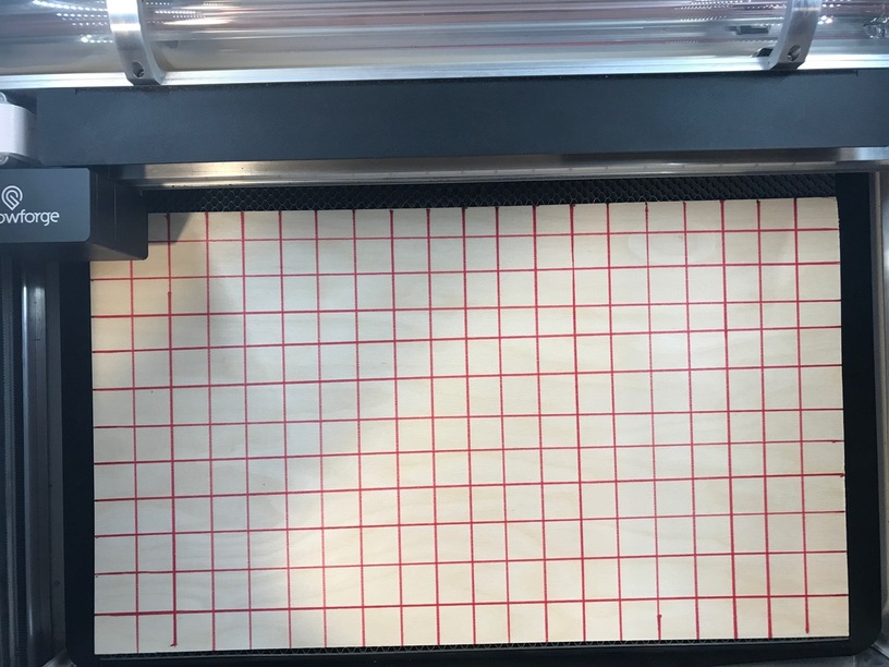
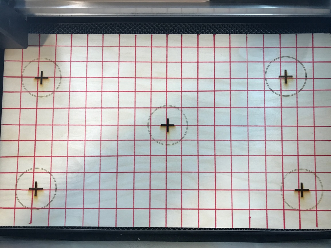
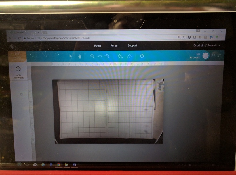
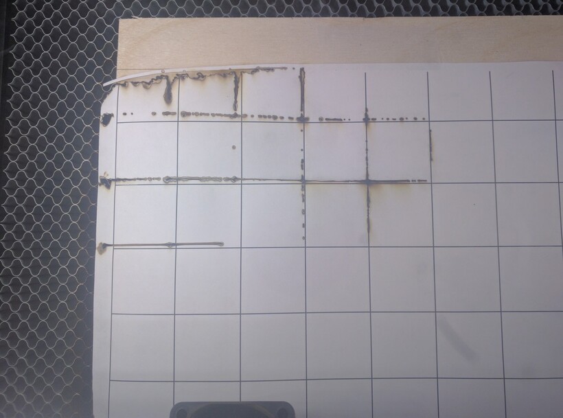
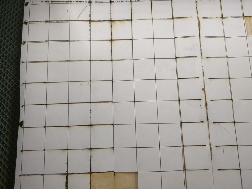
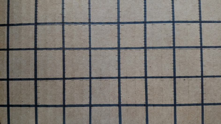
So I had this grid on a piece of BB 0.125" ply (my usual amazon stuff) with a red sharpie. Why red? Well because then the black engrave lines would be visible if this was a possible test to perform…
(sorry, hard to get a squared image, and too lazy to fix in PS - but it is)
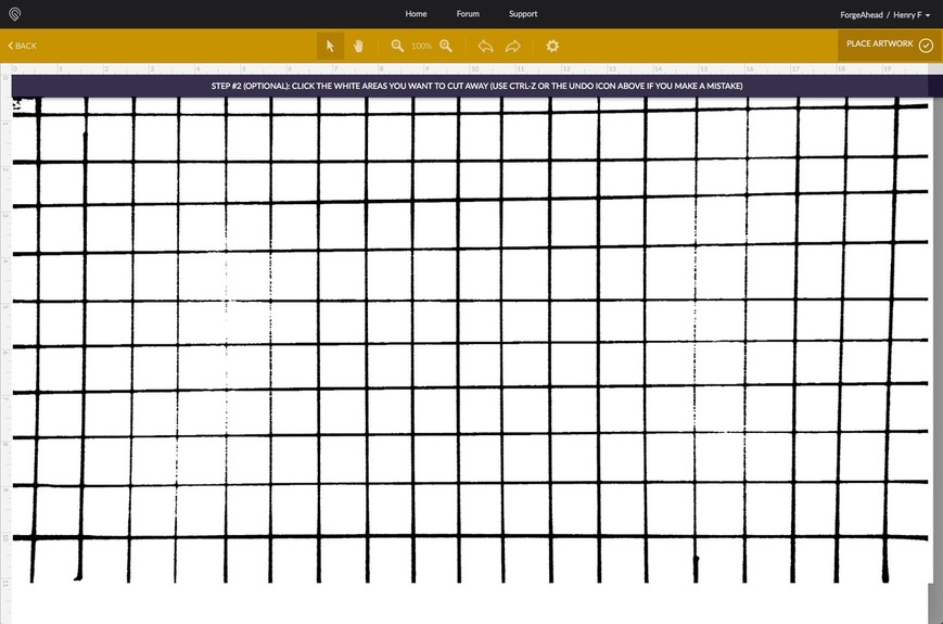
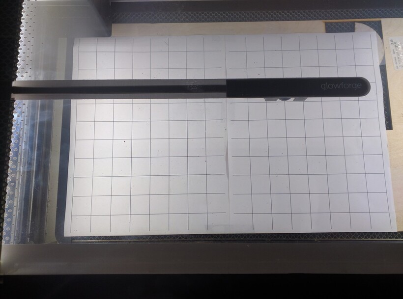
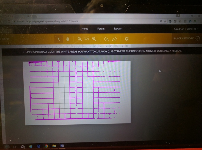
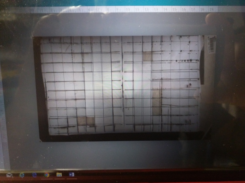
Now put it in to trace, and after adjustment with the shift-arrows arrived at a semi-reasonable trace (actually kind of meh, but after about 10 up contrasts the problem is the noise between the lines got too bad to be able to get good traces to show, so this is kind of not awesome scanning. I would bet I would get way better on my flatbed into AI, but this is what it is.
Tracing
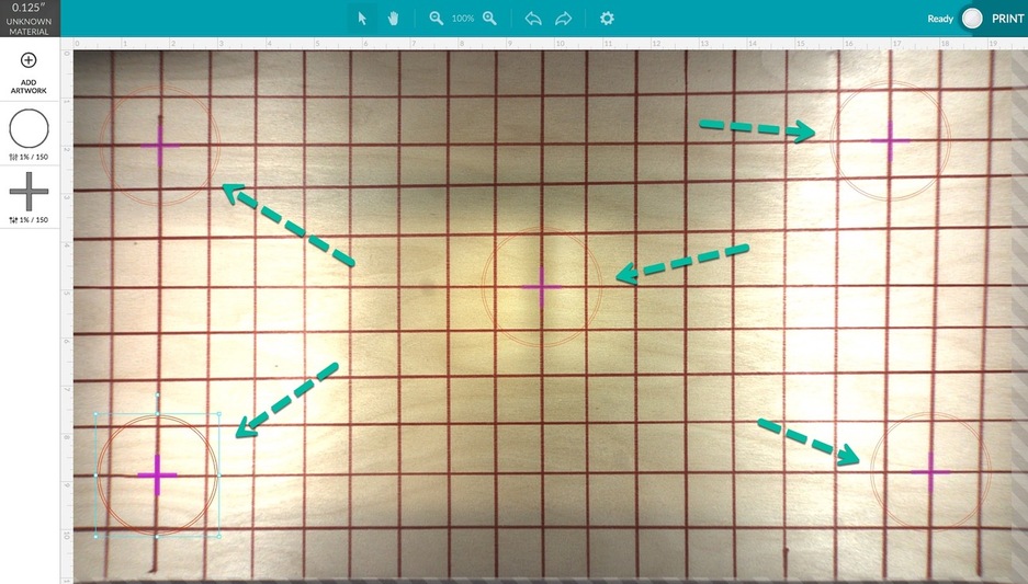
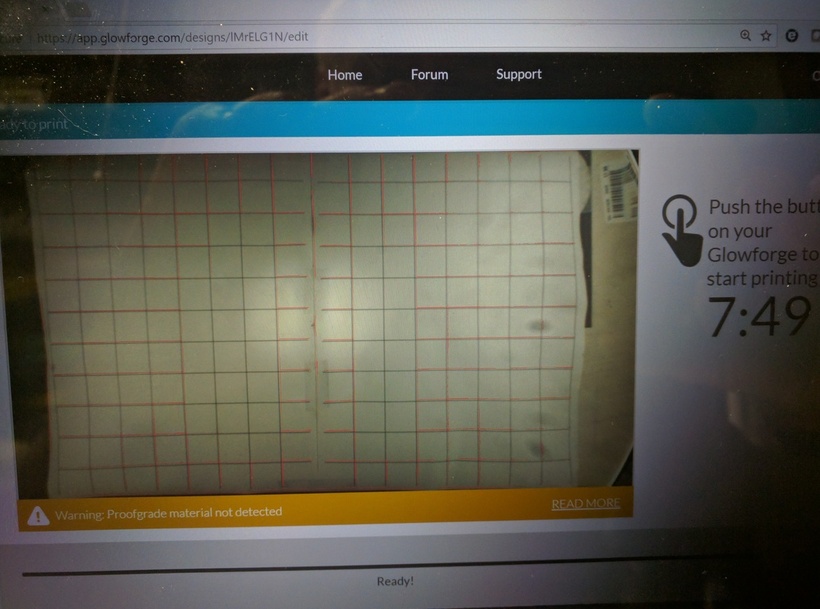
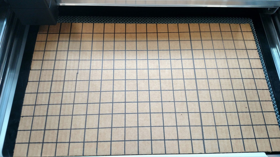
And now the fail:
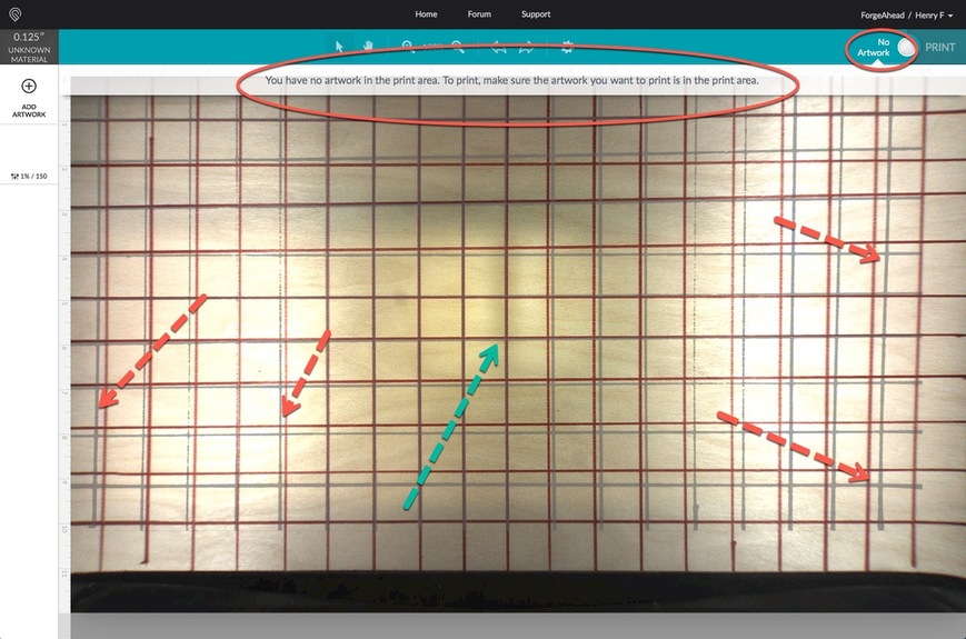
Fail 1: because the traced image is greater than the size it can engrave, instead of doing what any reasonable software would do (“would you like to crop it?”) or simply self-crop it, you can do absolutely nothing. Now of course if you could download, you can crop in PS, but that is not the advertised functionality here. So of course either GF needs to put a frame on their proof grade masking to advertise the actual traceable area (like in a video editor) or add crop, because otherwise this will annoy users.
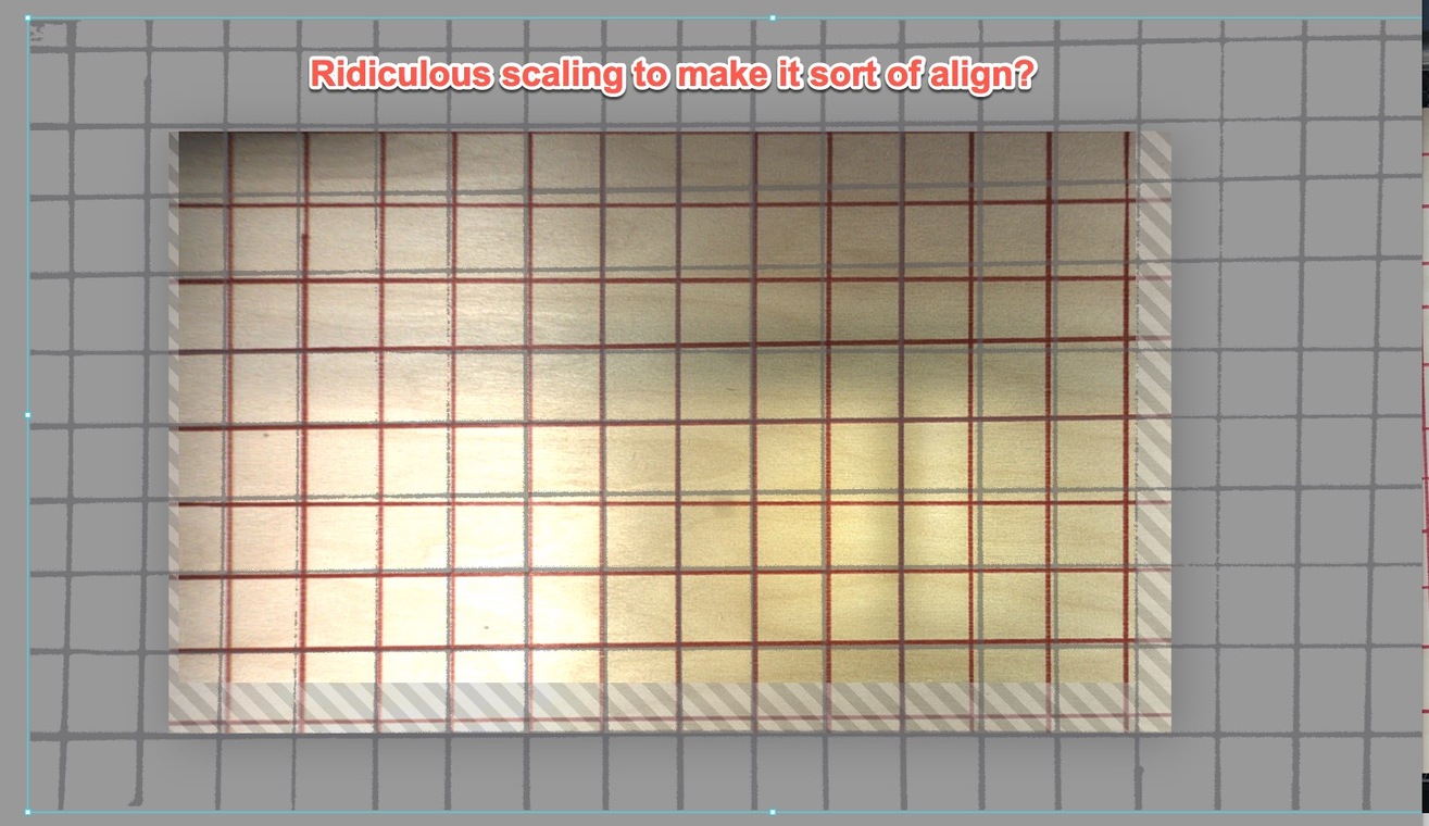
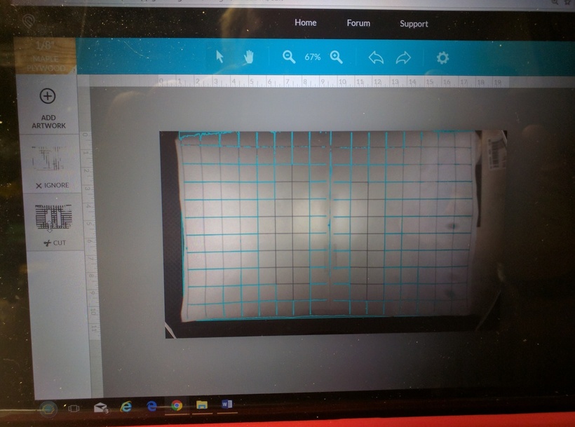
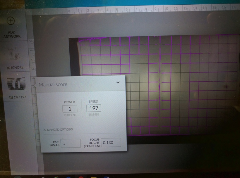
It also has applied a strange scale that no matter what I did in GFUI I could never get a scale that fit (the scaling is way down, so by zooming way, way out in GFUI I can make it fit, but it is huge!
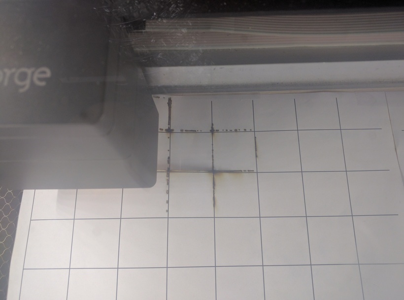
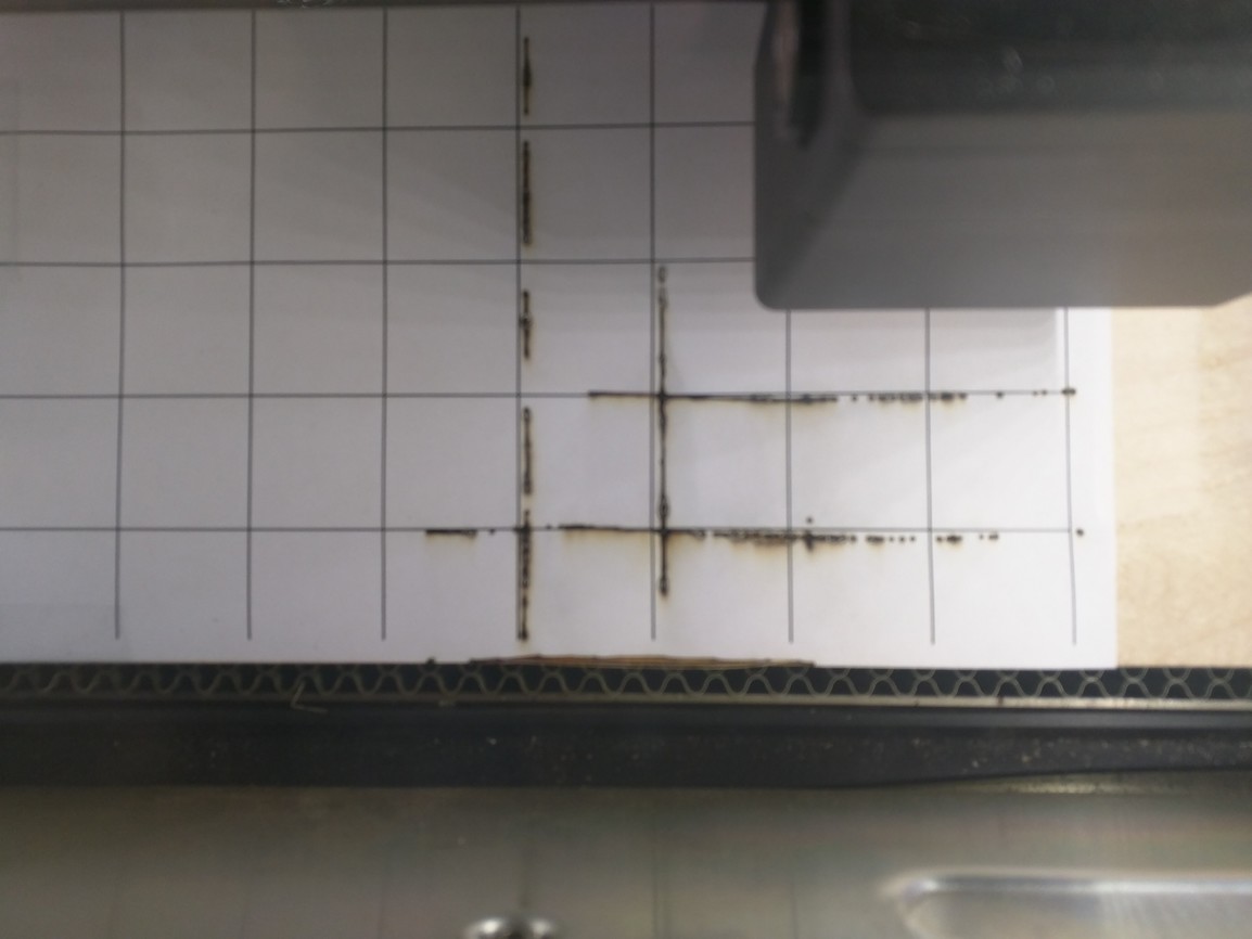
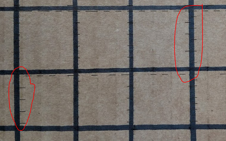
Fail 2: the alignment is clearly off. Now in fairness this is a PRU with a slightly torqued door hinge, so the camera is likely slightly tilted, so I am NOT taking points off for the fact that it is misaligned differently between left and right sides