I got my machine a few weeks ago, but it seems like either the cloud system is not sending the information correctly or the laser machine camera is messing around.
I am making some basic cards 300mm X 150mm with a score line at 150mm across. But the score line isnt in the correct place and makes the fold wrong.
But i dont know if the camera is to blame because when i print a 300x150 (with score line) from my printer then place it on the bed. There is no possible way of lining the drawing up to the print (all drawings come from AI cc). even with registration marks (lines or dots) is will not line up using the camera.
Basically am i asking to much of my machine? or can i make it do what i need?
What you are describing is a Print and Cut file…it’s not something the laser is designed to handle without a jig at the moment. (Although one day, I’m hoping they will get the visual alignment with the camera squared away enough to use it that way.)
If you want to use it that way now you are going to either need to create a jig for your cards, or use indexing marks of some kind on it.
The jig is quicker, but when inkjet printers print on paper products, the image can be shifted quite a bit because of variances in how the paper gets fed through the machine - the feed tray guides can be a little loose in most cases so you rarely hit the actual printing in the same place twice.
This is what is causing some of the variances. There’s nothing tying where it’s printed on the paper to the cutting and scoring lines you’ve created, and visual alignment isn’t close enough yet.
There is a tutorial for creating indexing marks on your paper and using those to align the print with the cuts and scores here:
That’s one of the methods we use to make the laser do a Print and Cut file.
The software on your Glowforge is responsible for ensuring that the print lands on the material in the same place as the preview. When you’re done with a print, let a new image load. If the print appears on screen far from where it was supposed to go, you may have an alignment problem.
Most alignment problems come from the material being closer or farther from the camera than expected. While the software is still improving, you can take these steps for the most accurate alignment results:
Use Proofgrade™ materials.
If you don’t use Proofgrade materials, use a precision set of calipers to measure your material, and enter the thickness in the “uncertified materials” dialog.
Use material that is not warped or tilted.
Place your design near the center of the bed.
Clean the area underneath your crumb tray, particularly the four indentations on the floor.
Reboot the machine. Alignment can drift over time, particularly if you bump the head of your Glowforge while removing material.
Should you finish all of these steps, and find that you have an alignment error of more than 1/4", please contact us so we can investigate.
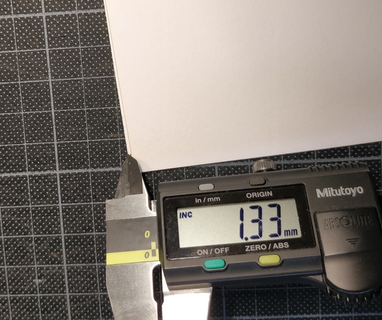
OK so we have tried what has been suggested but have just realised what we think the problem is. We think that the servo’s are not running together, because using AI we have created a test rectangle with a score line in the middle (w:300 X h:150). When we fold that over, we are getting a 1.33mm (0.0523 Inch) alignment difference between the sides.
Can someone try this for themselves and see if you are getting the same error & is this considered to be within spec?.
Don’t think you can rely on the forge UI for this. You will want//need some svg design work.
I made a pile of earring display cards a few times using a print//cut method. It isn’t hard, just tedious.
Make a design of the items to print//cut on an 8x11 worksheet.
Transfer them to a 12x20 worksheet and center them.
You can eliminate the printed stuff and just color code the cuts and//or scores.
This will be the cut svg design.
Print some trial sheets from the 8x11 design.
Nail a tack board to the crumb tray so it will not move in any direction.
(remember to add the tack board thickness to UI parameters).
Center one of the print sheets on it and attempt a cut using the 12x20 svg.
Examine how far off the cuts are. Shift the paper to compensate.
Mark the tack board for paper placement once aligned correctly.
Once lined. You can replace as many sheets as you need and cut them. Just stay in the UI window as you replace the printed sheets and redo the print button. I did them one at a time (did not want the cards flying all around in there), so it became tedious, but it worked very well.
Initial centering without camera. Used an L shaped wooden item. It is 12.75 x 5.68. When placed against the left side and bottom it points to the (10, 6) point of a 20x12 work sheet. Identify this as the center of the printed page and cut will be right on or very close right out of the gate.