I know this has been covered before, but deserves more attention.
My lid camera does not show the top or left edges of the bed, thereby making those areas of PG material unusable.
To compound the problem, the bottom and right edges are software-blocked, limiting the usable bed area even further.
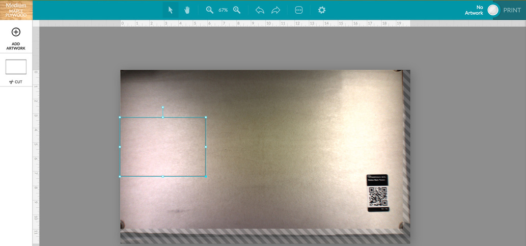
For the image below, I’ve placed a 3/4" diameter magnet in each corner of a new piece of PG plywood:
The bottom left and top two magnets are almost invisible, area unreachable
The bottom right magnet is fully in view, but the area is also unusable
I guess my request is, either show me the top left corner so I can use it, or unblock the bottom right corner so I can use it. Or both. I’m currently missing out on ~1.25" of usable space on each axis.
EDIT: To be clear, my request has little to do with usable area, I know that’s limited for now. I’m more interested to know if my physical camera is pointing too far down-right.
Yup. I second this. There are A TON of issues with this software, having to manually aligning the print head to the camera before turning on also is a load a BS.
If my design calls for less material than a full sheet I will cut it on the miter saw first.
Doing an order of 1000 1-1/2" round tokens, cutting the sheet at 9-1/4 gave me two pieces where 48 would fit on the smaller piece and 56 on the bigger one. All I lost was the saw kerf.
The software is still beta, but you can plan the best material size for your needs and eliminate waste - which is good deign intent anyway.
You will want to save any lengthy scraps, I have found many uses for them like running tests for settings.
IMO, lining up the head under the camera saves me a few seconds in the homing routine. A couple of sharpie dots gives me an instant reference and is no big deal.
I don’t want to derail the thread - but my head would bounce on occasion. If that happened, I would just turn it off and manually move the head. Yesterday, I turned it on, it bumped the head and I just let it do its thing - it didn’t bump again and moved horizontally straight under the camera.
Edit for clarity: that it recovered on the calibration procedure, without my interaction
I’m a CNC and 3d printer guy, so I see the value of not having a stepper driving it’s hardware, especially as expensive as the laser head, into the gantry every time I turn it on. So I skip all that and manually align it to the camera every time. Shouldn’t have to, it’s a MAJOR annoyance, but it’s piece of mind.
Then don’t do it. Turn it on and see what happens. Perhaps they’ve figured out a solution they are satisfied with and pushed it along with the camera updates. It’s easy to get stuck doing things just because it’s a habit.
Not really losing space because of the camera view. The bed is far bigger than the cutting area. Currently they allow 11 x 19.5 with plans to go to 11.5 x 20 or so for a cut. Less for an engrave as shown here. (numbers off the top of my head). Even if the camera showed the whole bed you would not be able to use any more than you currently can. There are a combination of hard stops for the head and S/W limits for deceleration.
My car doesn’t come with a note that says 5% of the time when you put it in reverse, it will go forward instead, so we recommend pushing it to the middle of the driveway before attempting to back out.
Hard to see why we will be limited to 11.5" when they finally sort out the camera. Losing the ability use all the standard 12" material width is a big downside. The Y axis appears to able to move more than 12" and there isn’t any need for engraving overshoot in the Y direction.
Yes with a low torque belt drive I don’t there is any big shock that will damage the motor and none of the other stuff on the page seemed relevant. So I don’t think the motor will ever be damaged.
The topic may as well be “water is wet”, it’s completely uncontroversial. Yes, the edges are unusable. The usable cut area is 11"x19.5" due to semi-mysterious software limitations. It’s supposed to eventually reach 11.5"x20" to match the specs on the Glowforge web site, but as with all future features and improvements, there is no ETA. We’ll be told about it when it’s being rolled out and not a moment before. There isn’t really anything new to say on the topic.
Except to say that, when the day comes when the software limitation is lifted, the problem will still exist if the camera is physically unable to show the top/left edges of the bed.
… which I guess was the root of the question that I never actually asked in the original post.
So GF, is this a physical camera misalignment, or is the viewable area (ignoring usable area for now) something that can be fixed in software?
I think it loses 0.5" just because the camera homing can be 0.25" out in each direction. It can’t go right up to the ends of the axis until the camera is accurate without running the risk of hitting the ends.
I don’t think the head crash during calibration is connected. That is just some faulty vision logic.
Once it has calibrated it shouldn’t hit the ends (although there does seem to be something in the front right corner it can hit). But if it is only accurate to 1/4" in the centre you need an extra 1/4" each end.
And any wiggle room in the lid adds to the uncertainty of absolute position within the axes.
Thanks for the reminder! The last time the print area was enlarged, I took a 12" square of ply and “found” all four visible corners on the bed by setting it in place and refreshing the bed image. Rinse, repeat. In short order I had all four boundaries marked with sharpie lines (on blue tape) on the plastic bed frame. Huge time saver when trying to optimize material use. Did the same thing to mark the printable area (also on tape to facilitate changes). Took about 20 minutes to get it all dialed in.
One of these days, I’m going to make a set of nifty registration blocks à la@Jules to place on the left and front to speed placement even more.