yeah, I mean I would hope they are working on it, but for now, I wish there was a sighting option. I have been trying to “calibrate” mine based on the setup @eflyguy showed, but I’m not getting anywhere fast. @eflyguy did you just make the file by adding lines at tick marks? How did you align it with the base? Thanks for any ideas.
I’ll try to explain it differently…
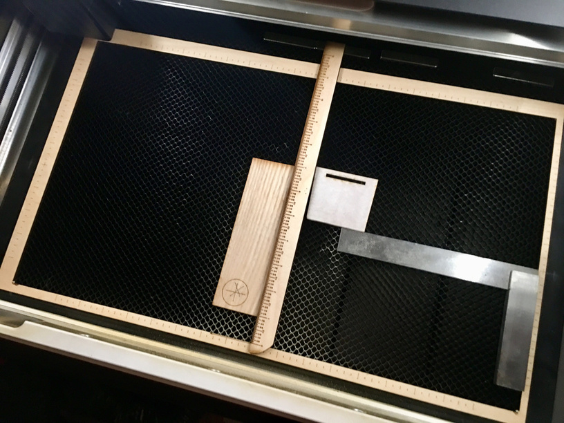
If you align things in the GF UI to what the camera is showing you, it will likely be off. That’s what my first picture shows. The purple designs ended up being all over the material after scoring.
If you align them instead to the rulers in the UI, it will be exactly where you expect it to be, every time. This, of course, assumes you know where on the actual bed the ruler marks should be!
So if you make “rulers” that mirror the ones in the UI (by putting design lines at every tick in the UI ruler), then using those for alignment will always be accurate. I used the outside of a piece of 12x20" material to score the marks into those “rulers”, it’s a near-perfect fit onto the tray when pulled down against the lower edge, so repeatable if I remove it.
I didn’t actually create a bunch of lines in the GF UI- I did it in Inkscape, then moved and scaled in the UI to match the ruler marks.
3 Likes
Does this work for you across materials with different thickness? I am not sure why but I cannot brain today. Thanks for your helpful response. I’m going to see what I can make in illustrator today and then when the cold air returns I can try lasering some 
I’ve used various materials but nothing thicker than 1/4" - I haven’t actually tested the alignment with different thicknesses because it’s never been an issue, but next time I fire it up I’ll try to see if the height makes a difference. I am pretty sure it would on the camera image, but that’s the point of my rulers, I don’t use that for alignment, but instead my rulers.
1 Like
Thanks! my machine is currently out of commission (and I am in a pretty mad mood about it), but if support is able to get me back online I’m going to re-make your file. I had just finished aligning everything in the UI when it disappeared…
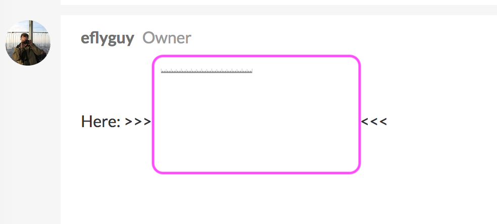
If you mean the ruler, I can set that up for you…
Here: >>>  <<<
<<<
3 Likes
Oh hey, thank you so much - Is this something that should just line up with the UI rulers? You saved me a lot of work, thanks again!
Yes - if you align and scale that pattern with to the rulers in the UI, then after scoring, anything you line up with with the UI rulers will be exactly where you expect it to be - relative to the ones on the bed.
The camera is way off, but the machine always knows where the beam is, and that is very accurate and always repeatable (unless they change something in the software).
1 Like
I really appreciate your help, thanks very much. This has been a huge source of frustration and hopefully I can get it working.
1 Like
I don’t see the file for the ruler.

Oh, I see it now. I guess you would import the jpeg into Inkscape and convert to svg file? I’m new at all of this so probably sound like I don’t know what I’m talking about … and I don’t.
I still don’t understand how to transfer the UI rulers to the ruler you made around the perimeter. A video demonstration would be awesome!
Actually it should save as an SVG file for you – right click and choose “save as.”
Got it! Thanks
1 Like
Then once you have it in the GF UI, check the scale - it should perfectly match the rulers on the edges of the UI workspace, like this:
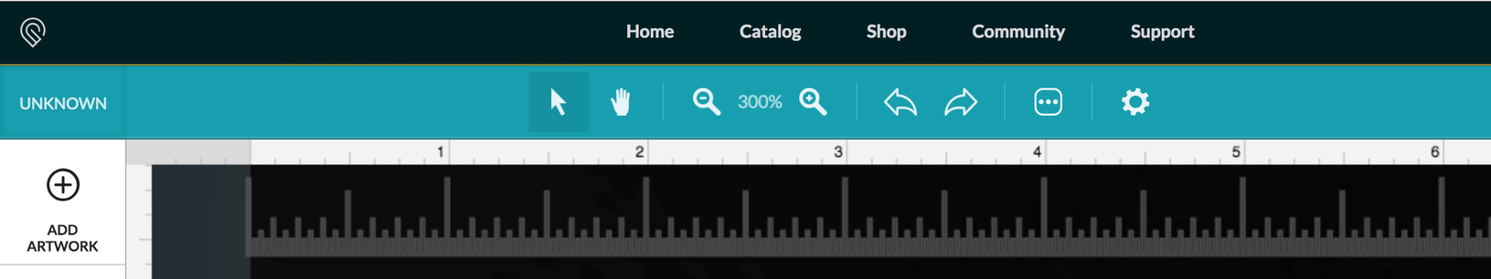
2 Likes
Let me know if I understand correctly and thank you for your help and patience. After making the ruler and placing it on the crumb tray, I line up the material I want to laser with a measurement mark on the wooden ruler. Then I place the design at the corresponding measurement mark in the GFUI. This seems like it would work well on the edges where I can accurately line up the two corresponding markers, but how do you use it on a larger piece of material or when trying to make alignments in the middle of the material? Also, did you cut out the ruler on a saw and then place it in the glowforge to make the measurement marks?
Part 1 -
Part 2 - I do have rulers for individual sides, but what I also did is take a full piece of PG material and figured out how much I would have left around the perimeter if I cut a box as big as will fit in the UI - it’s a bit smaller than the full size of the sheet, about 1/4=3/8 inch. I then took a simpler version of that ruler I shared earlier, and scored it onto that remaining rectangle, by moving it up enough so that the laser could reach for the “bottom” edge, flipping it around for the “top” edge, and then - using the pass-thru at the front - doing pretty much the same thing for the “sides”…
I had to be cautious to get the alignment right so my marks would be in the right place - I made pencil marks on the edges of the crumb tray to help align the “border ruler” for this.
Now that I have it, I can drop it in when needed (or hang off the side of the bench when not), and have rulers all the way around - just like in the UI.
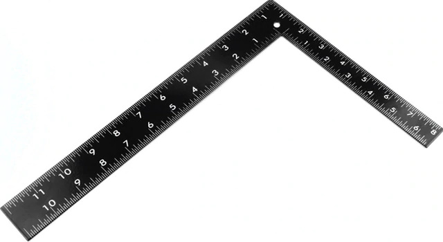
Imagine something like that square ruler but a complete rectangle that just fits on the bed, but is open completely where the laser can cut. Like a factory-calibrated ruler all the way around the crumb tray…
3 Likes