Over in the Harlequin Pen thread the idea was tossed around to offset the layers in the laminated pen blank in order to provide better glue adhesion. The original pen had all the layers stacked with the seams in register so the segments in each layer had but joints along the kerf. Sideways it would be very stable but weak in the vertical axis.
I wanted to see what the same basic design would produce if the layers were offset so I whipped up a model in Tinkercad.
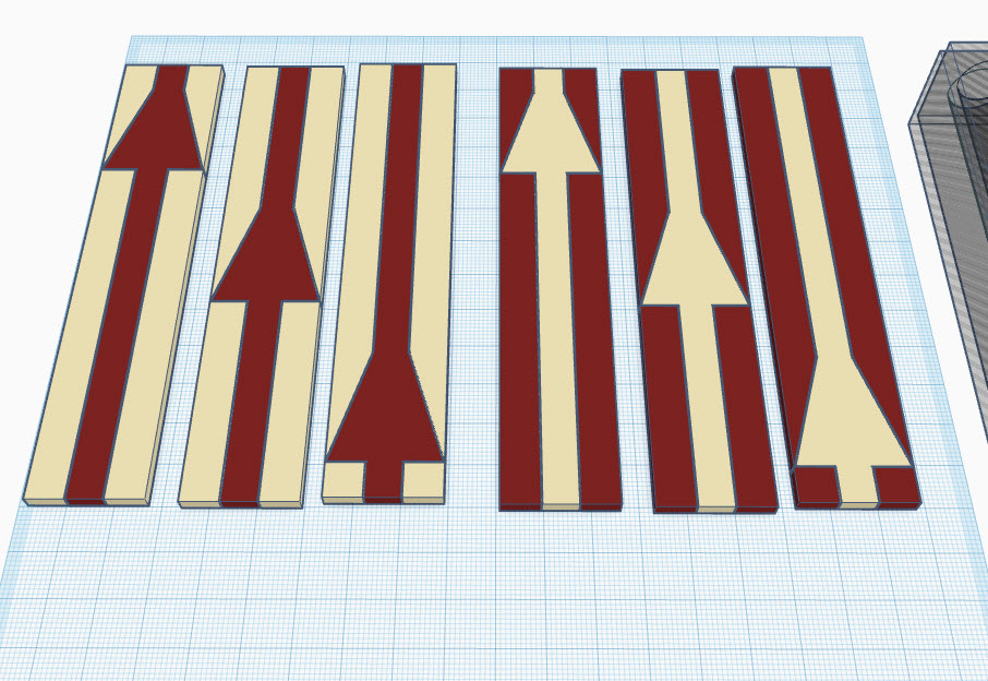
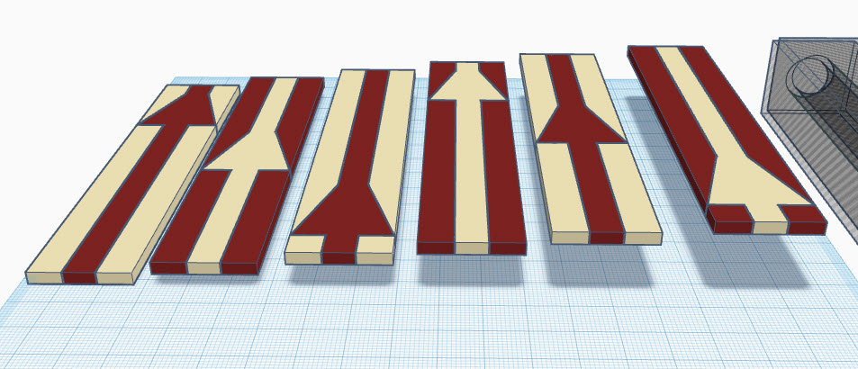
First I drew up three layers based on the original model but with the Y section offset. After importing to Tinkercad, I extruded the flat outline to 3mm layers - about 1/8 which is the nominal thickness of my wood stock. The layers started out like this:
Then they need to be stacked and centered on each other.
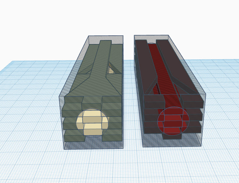
Once they are in register the two materials need to be split because the extrusion uses “Combine” and if the materials got combined they would have the same color. What is needed is to extrude the “walnut” and “maple” as separate pieces as shown here.
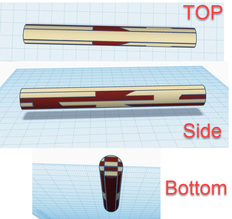
Putting the two extrusions back together shows us what the blank looks like after turning down to 14mm, the same thickness as the original.
If you want a better description of the modeling process I made a Pen Mold Visualizer Instructable with pix and video.
That tutorial is aimed at the intersection of 3D printing and woodturning but the process is the same for laser, once the blank is modeled. To make the 3D model for the pen mold I started with a flat SVG and extruded it in Tinkercad to full height.
To make the laser printed pen blank I also started with flat SVG, except I had 3 files which were each extruded to 3mm, repeated in contrasting material, then stacked.
Both processes end up with a (approx) 1"x1"x5" pen blank. Then an “extruder die” is made by putting a hole in the middle of a slightly oversize box, then inverting the resulting shape into a hole and combining it with the model.
Voila! The result is a visualization of what a pen would look like turned from the base model. In this case it saved me cutting the stock, assembling the blank and turning the pen tube since in the end I didn’t like the result. I did try it with several diameter extrusions but nothing looked as aesthetically pleasing as when the cut lines between light and dark intersect. (To me, anyway. Your mileage may vary.)
So, yeah, NOT made on a ![]() but I figured it is on-topic since the modeling technique might help others. Even if the project isn’t to be turned on a lathe. It might sound daunting to model up, say, 50 layers in 3D but it boils down to applying an extrusion to the cut files modeled for the laser. Want to make a laminated box? This is a way to do “what-if” to visualize the laminations with different stock thicknesses.
but I figured it is on-topic since the modeling technique might help others. Even if the project isn’t to be turned on a lathe. It might sound daunting to model up, say, 50 layers in 3D but it boils down to applying an extrusion to the cut files modeled for the laser. Want to make a laminated box? This is a way to do “what-if” to visualize the laminations with different stock thicknesses.
Hopefully someone will find it useful or it’ll spark an idea for something else.