So they only way I can see it would be able to square the gantry is to look at it with the camera and move the motors independently. However that would be very difficult to get accurate as the camera isn’t accurate. I have to conclude it does nothing at all and just depends on the wheels pulling it square before power is applied, but they don’t.
It’s all a result of the unfortunate design choice to not include home switches. A standard gantry would have one on each side of the gantry and one for the head movement on the gantry itself.
The gantry would be pulled straight by independent y movements as each side senses their independent home switches. This would result in perfect squares and would have given us a known zero coordinate system. Alas, we seem to be stuck with camera alignment, which at least up to date does not seem to be very accurate and does not seem to address squareness at all.
Finding some unused GPIO on the PCB to add home switches and this would be the first open source improvement that I would get excited about. Ethernet would be the second…
3 Likes
I had this with my first Glowforge. I was able to use a machinist’s square and get the gantry square to the Y rails. This solved much of the alignment issues, but there was still a small angular error. I hope the replacement solves it as it causes all my boxes to come out a little wobbly.
1 Like
The only easily accessible free GPIO’s on the factory control board happen to be for the un-populated Ethernet interface.
![]()
2 Likes
It must be doing something though, yeah? Because not everyone is having issues. I just double checked a bunch of my cuts over the past month and they’re all square.
It might just rely on the V wheels being perfectly aligned so it happens to start out aligned. Unfortunately that is not a reliable way to do it.
If you add a bit of skew to your gantry before starting up the machine does it correct it?
@dan has mentioned in the past that current stepmotor drives can detect obstructions or reached limits without the need for physical switches, the way that trinamic drives do on new prusa 3d printers. he said that all in needs is software implementation
1 Like
Don’t think the drivers can, they are too old. I think Dan was referring to the accelerometers in the head.
I might be wrong, but reading the whole thread the only thing he could be refering to seems to be the post right before his, talking about the tmc2130 drivers.
also, even w old drivers, if motor amps or load can be detected, especially on a laser cutter where there is no load other then accelleration, software can technically detect limits.
1 Like
There probably is an I2C bus in there somewhere, which could be used to add an expander to read the flags…
The GF uses Texas DRV8825 drivers that don’t have any missed step detection capability. Stepper current doesn’t increase when you stall them because the drivers are constant current drivers.
Like @palmercr said, this is not possible with the stepper drivers in the GF.
There is an accelerometer in the head, but it is not currently used for anything (that we can tell, anyway).
Currently, it’s not uncommon for the head to hit an obstruction (like the side of the housing) and keep on going.
1 Like
There are 3, in fact.
1 Like
Also, as @dallasnyc pointed out, the gantry hits the back at one side before the other so you can’t use that to square it.
I stand double-corrected…
1 Like
It seems to, yeah. I pushed one side back until it was just visibly off. After the first calibration (which might have taken slightly longer than normal. Or maybe I was just paying more attention than normal), it looked back to straight and the square I cut was just very very slightly off (still fit in the cut out in all possible combinations, but not perfectly. But much more square than OPs). So I turned it off and on again – is there another way to force calibration? – and it’s back to normal after the second calibration – second square cut is as spot on as I’m able to measure.
Maybe that’s because I didn’t skew it enough? It actually requires a lot more force to do than expected, and I was scared to break something in the name of science. Especially since I’m probably the last person who would be able to fix it. It might also be that machines that are square are more likely to or more easily return to square? With the machine off, if you push the gantry back as far as it can go, that would theoretically square it, yeah? If you did that to a not square machine, I wonder if it would return to not square again over time.
I genuinely don’t know how anything works. I’m just always full of theories.
1 Like
Thanks everyone’s for their input.
Correction, it’s the right side that pushes back more…
The whole right side of the gantry moves pretty freely. The interesting thing is that is pretty much springs back to it’s original position when you role it back and forth with two hands. So I am unclear how it does that.
The right side pushes further back than the left:

The right side of the Gantry can rock back and forth but returns to original position:

The wheels on the left side are loose and move back and forth:

The bottom wheel is on a spring, which allows you to slightly lift the gantry from the side rail, this allows me to jiggle the wheel. Both top wheels on the right side are loose like this. The left side wheels are snug.
So my question is to those who have a Glowforge, are the conditions I posted above normal?
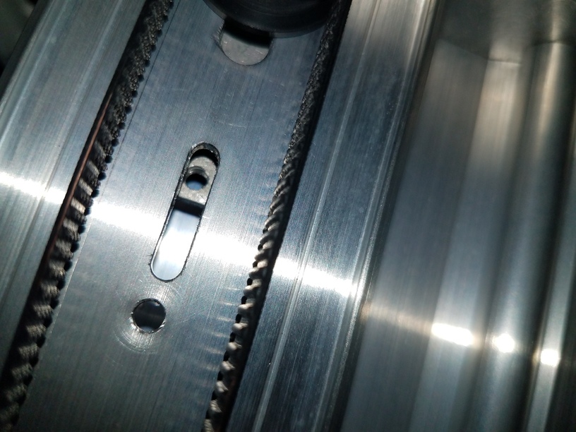
Lastly, taking pictures from underneath the gantry, I see a spot where it looks there should be a screw. It looks like it is connected to the right side wheel for the X- belt. That said, the X belt is snug and doesn’t move. So again, if anyone can check if they have a screw there or not on their Glowforge?
D
2 Likes
I have a Shapeoko2 milling machine that has the same sort of gantry. Without power it is a little out of square because of tolerances but it can be pulled straight by the motors if they have independent drivers and limit switches. To get it to stay square without power I would have to shim the end plates to get the V wheels exactly in line.
The problem is Inventables didn’t cut the gantry extrusions exactly the same length and the V wheels are not very accurate and they are spaced on washers that have poor thickness tolerance.
So really with this sort of axis you need to actively square it. Otherwise it depends on precise alignment of some fairly imprecise parts with no apparent means of adjustment. That isn’t a suitable design for mass production.
My screw thing looks the same as yours on both sides (if thats the thing at the almost-very-back of the unit). But mine doesn’t move like yours at all in terms of the springing back that you’re seeing. When I push it back as far as it will go, it just stays there. I can’t tell from the video (I see my glowforge from a lot less top down. Lol), but I think mine might push back further than yours does. Not positive about that though.
Seems like it relies on just the wheels on one side to hold it square if the other end is sprung. That seems like they don’t trust the rails to be exactly parallel and have sprung them to stop it binding.
Any sign of shims or adjustment on the side with the fixed wheels?