I encountered a problem regarding the focus height and therefore the result of my engraves. Maybe it’s just the settings so I hope you can help me.
I’ve a Glowforge basic.
The tests were made on 3mm MDF,
I measured approx 0.135 inch in thickness.
For my customers I often engrave thin lines on products they already have, mostly on 3mm material (acrylic and MDF).
From time to time I have the problem that the engraved line is thicker and slightly misaligned - the laser was out of focus.
Most of the time, the problem occurs when I engrave transparent acrylic because the auto focus does not work here.
The idea was that I’ll do some tests to get a fixed value I can set the focus height of the glowforge to so I don’t need the auto focus.
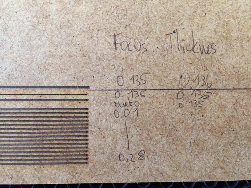
But… the results are confusing - see picture.
As I said, the “material thickness of uncertified material” is set to 0.135 inches.
The “engraves” were all cuts, speed 200, power 20, 1 pass and different focus heights: from 0.01 to 0.28 aaall lines looked exactly the same. This just does not look right to me.
After that I set the focus height to “auto” and got exactly the same result.
Focus height set to 0.135 inches with material thickness set to 0.135 gave the result I aim for.
I was curious if 0.135 focus height is the exact right setting so I set the focus height to 0.135 and the material thickness to 0.136 (to be sure, the focus height isn’t set auto). The result was the worst.
So, after all this testing I’m very confused.
How can I set the focus height to a fixed value and still get the thinnest line possible…?
We had the discussion with dan at one point and he suggested that based on their much more extensive testing, max speed at high power with a focal point set at the surface of the material gave the thinnest (cleanest) lines. That’s also what your testing showed.
Try speeding it up, and upping the power to full. Messing with the focal point might not be as effective at those slow speeds.
When using uncertified material, you put the material height into the material thickness box. That populates the focal height boxes for any job operations.
Then, two things can happen:
If: entered Material height and focal height are the same values, then the scanning process when you hit print determines the actual material height and sets the autofocus.
Or
If: entered material height and focal height are different, it will still run the scan/autofocus operation but disregard it, and your focal height entry will be used.
For example:
That process used the autofocus measurement.
You said it’s 3mm MDF. But are inputting .135” - is it actually measuring that thick? Also, you can switch the metric in the UI now. Click the little gear icon on the top of the screen and you can select metric.
All of the testruns are with 200/20 and the thicker lines are cleary out of focus which means they are out of position as well. Last point is a real problem since the engraves on customer’s material must be as precise as possible.
So, yeah, maybe I could speed this up but sadly it does not help me at this point.
Blockquote
If: entered Material height and focal height are the same values, then the scanning process when you hit print determines the actual material height and sets the autofocus.
Or
If: entered material height and focal height are different, it will still run the scan/autofocus operation but disregard it, and your focal height entry will be used.
That’s what i knew so far.
-What is odd: 0.135/0.135 and auto/0.135 gave different results (?)
-I tried so many different foucs heights but got allways the exact same result. and none of them were as thin and in the right position as 0.135/0.135
The 0.135 inches are measured from ma acrylic with paper on it, the 3mm mdf or acrylic is 0.115 to be fair. But since I used 0.12 inches and so on in my test run I don’t know why I don’t get the same result as with 0.135/0.135
I just tried some different settings and registered something strange.
The moment when the glowforge realigns his focus height, the laser-head stops for a moment - so far so good.
As shown in my first post, I used a test-file with 10 (or so) lines. Each of the lines got another color in Illustrator, so I could give each line a different focus for testing.
In my test run a minute ago I wanted to test some more lines so I uploaded the file two times in one print-job.
Each of the 20 (or so) lines got a different focus height.
Then I hit the button.
Now the strange thing happened: the first 10 lines were lasered in a row, without realigning the focus height. Then the head stooped, realigned and after that the second ten lines were lasered - whitch a different result but still the ten lines had the same focus (although given different values).
I hope you can understand what I am trying to explain
So: maybe I can find the right fixed focus height now.
But: it seems, the UI has little bug as the focus height didn’t change although having different values
Oh wait - I might have an idea of what could have happened…
Any time you open a new file, the first thing you want to do is to measure the thickness of the customer’s material accurately and enter that value for the material thickness at the top of the left column.
That does two things…it corrects the camera distortion for the algorithm that they use for placement of shapes on the screen, and it preloads (easy-loads) the focal point for you into all the slots for the various operations you have set up. (The default is to set the focal point at the surface of the material with this program, so that’s all you have to do to set the focal point. Only override it manually if you want to defocus the engrave and make the lines thicker deliberately.)
BUT…if you leave the program running and just switch materials in the bed, you might need to go in and check to make sure that the current focal point is set correctly for the new material, especially if you have manually hard-coded a value for the focal point in the Manual settings. From what I’ve noticed in the past manually hard-coded settings do not update automatically using the Unknown Materials easy-load button, and you’ll need to go back in and reset the focal point to the surface of the material for each operation again.
I’m pretty sure that anything hard coded in the Manual settings will override the easy-load values that we get from using the Unknown Materials slot, and given that they are now Auto-saving settings, I’m not sure if they get updated with a new material…probably something I need to check one of these days…just remember to give a quick check to the focal point settings on an operation where the line width is critical and make sure that what you see in there is the exact thickness of the material currently in the bed. It might not be updating depending on how you are entering the values. So the focal point for all of those lines you did above might not have actually been updated if you were using the Unknown Materials slot to do it. (Which could explain why they all looked the same. They all were the same.)
Anyway, try some experiments along those lines and check the values in the slots to see if what you are entering is updating when you change it…
Hey Jules, thanks for the detailed instructions - but I’m pretty sure that’s not my problem
I’m a huge fan of the autofocus and use it as often as possible.
But as mentioned before, sometimes I’ll have to deal with transparent material and therefore the autofocus does not work as intended (the red dot goes right through the transparent acrylic).
When I want to compensate this little problem, it does not work as I want it to.
Lets say I have a 3mm acrylic. Normally I’d use the “Unknown Material: 3mm” with “focus hieght 3mm”, so the auto focus will do the work.
When the auto focus does not work, I’ve to write the focus height manually. But even if I use 2.99 or 3 (with Material Height 3.01 or so, so that the auto focus does not kick in), the result is faaaar from the result with auto focus.
And I don’t know why. I tried so many different settings but won’t get the right focus height the glowforge gets from autofocus.
I have two ideas how I might solve it in a different way:
is it possible to see the value, the glowforge is measuring when autofocus? This way I could use this exact same value when focussing manually
is it possible to give the glowforge the exact position, where it shall measure the thickness? Sometime the laser-head is positioning itself directly in the middle (beneath the camera) , sometimes in the middle of the printjob (or so).
Since I use transparent material I maybe could put an non-transparent material in the bed and say “glowforge, please measure the thickness over there!”
The focus mechanism has only a certain level of precision; it’s not infinitely adjustable. If I remember correctly, the focus mechanism moves in intervals of .028" (so 0.00", 0.028", .056", etc.). I’m not sure what values you gave your test, but if any values you gave fall within the current range of focus, the head won’t pause to change focus.
I’m not sure exactly why would they be out of position? If the operation is out-of-focus (or selectively defocused), it shouldn’t change the actual position of the engrave/cut/score. What will change the apparent location is entering in an incorrect value for the material thickness. The material thickness box applies a value to the dewarping algorithm used for the lid camera image. The current spec calls for up to a 1/4" tolerance in accuracy between the overlay preview and the actual cut (with an accurate material thickness entered). If the material thickness entered isn’t accurate, all bets are off; the overlay accuracy degrades very quickly.
It might be worth pulling your crumb tray out and making sure that it is completely clean, especially in the divots that the tray sits in. Also, make sure it is firmly seated in those divots when you reinstall it. The manual focus assumes a 0" point at a predetermined distance from the head. If the crumbtray is unexpectedly higher than what that 0 point is, it could maybe explain why autofocus is giving you the lines you’re looking for, but manual focal heights aren’t. Does that make sense?
Unfortunately not.
Unfortunately not. But, it should always use a spot within your design.
One of the things often done with the transparent materials is to use a transfer tape (similar to what’s on the proofgrade materials) so it gives something for the red dot to be read from.
Blockquote
The focus mechanism has only a certain level of precision; it’s not infinitely adjustable. If I remember correctly, the focus mechanism moves in intervals of .028" (so 0.00", 0.028", .056", etc.). I’m not sure what values you gave your test, but if any values you gave fall within the current range of focus, the head won’t pause to change focus.
Oh…oooooh! Thanks!
I think my interval of testing was 0.02 inch
Blockquote
I’m not sure exactly why would they be out of position? If the operation is out-of-focus (or selectively defocused), it shouldn’t change the actual position of the engrave/cut/score. What will change the apparent location is entering in an incorrect value for the material thickness. The material thickness box applies a value to the dewarping algorithm used for the lid camera image. The current spec calls for up to a 1/4" tolerance in accuracy between the overlay preview and the actual cut (with an accurate material thickness entered). If the material thickness entered isn’t accurate, all bets are off; the overlay accuracy degrades very quickly.
Look at the Picture above. The second line (0.135/0.135) is the autofocused one.
All other lines are defocused.
In theory (and the file) the lines are perfectly aligned, means they are only repositioned in y, not x-axis.
But as you can see in the picture: defocused cuts and engraves tend to “move” about 1mm to the right. And this has nothing to do with the actual picture of the camera since there isn’t any moving of the lines in the UI.
Blockquote
It might be worth pulling your crumb tray out and making sure that it is completely clean, especially in the divots that the tray sits in. Also, make sure it is firmly seated in those divots when you reinstall it. The manual focus assumes a 0" point at a predetermined distance from the head. If the crumbtray is unexpectedly higher than what that 0 point is, it could maybe explain why autofocus is giving you the lines you’re looking for, but manual focal heights aren’t. Does that make sense?
Makes sense, yes. I’ll go check this.
Blockquote
Unfortunately not. But, it should always use a spot within your design.
Sometimes yes. But sometimes the head will move just under the camera (like it does when calibrating) and sets the red dot there. I think it is when the design is pretty small but I’m not quite sure.
Blockquote
One of the things often done with the transparent materials is to use a transfer tape (similar to what’s on the proofgrade materials) so it gives something for the red dot to be read from.
I use the paper everytime I create some new stuff, my designs. But, so far, I don’t use the paper for engraving stuff from customers… if I don’t find another solution I’ll go for the paper but this’ll be more work
Unfortunately, after much investigation, we’ve determined your unit is experiencing a focusing issue we can’t resolve remotely. I want you to have a reliable unit, so I’m recommending we replace this one. I’ll be in touch via email to sort out the details. I’m so sorry about the bad news.