I am still blown away at how this community just jumps to help each other! So much so that you’ve inspired someone outside of the forum to write up a guide to help with this inkscape inlay challenge. While we usually don’t do this, we thought that it would be immensely helpful and the solution was so elegantly written that we couldn’t keep this great nugget for ourselves! This could be a great tutorial piece too ![]() A big thank you to Kristen!
A big thank you to Kristen!
Here it is:
Paths in Inkscape
You can edit text in Outline Mode if the text has been converted to a path. There are two methods I am familiar with that allow you to generate these paths.
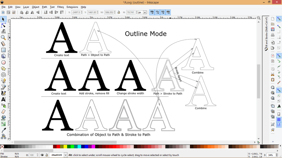
Path > Object to Path (creates path along the stroke)
- Create text.
- With the text selected, go to Path > Object to Path.
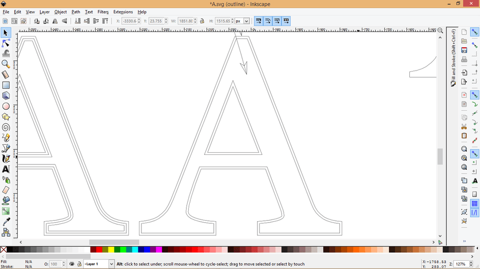
- Visually, the text might look the same, but if you view it in Outline Mode, you will be able to see the paths. If you’d like to see paths in Normal Mode, add stroke and remove the fill. If necessary, adjust the stroke width.
Path > Stroke to Path (creates path around the stroke)
- Create text.
- Add stroke.
- Remove fill.
- If you’d like, change the width of the stroke.
- Path > Stroke to path.
- Visually, the text might look the same, but if you view it in Outline Mode, you will be able to see the paths. If you’d like to see the paths in Normal Mode, add stroke and remove the fill. If necessary, adjust the stroke width so you can see the paths.
- If you’d like, you can break it apart (Path > Break Apart) to delete parts, or select specific parts and combine (Path > Combine) those.
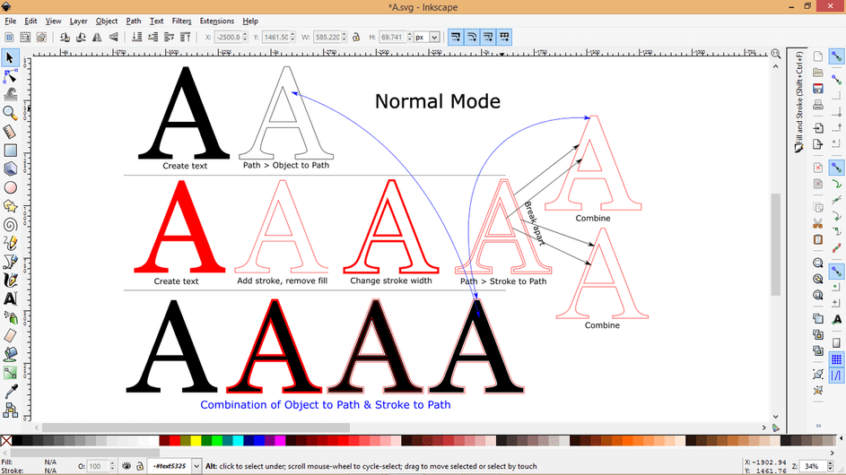
You can combine these methods to create your own outset (one that isn’t rounded out like you would get if you used the Offset or Outset tools)
- Create text; make it the size you want.
- Convert that text to path (Path > Object to Path).
- Duplicate (Ctrl+D) the object you just created.
- The duplicate copy should be selected. Add stroke and change it to another color (like red) so you can see it.
- Remove fill.
- Change the width of the stroke to a value that is double your desired outset; since you want an outset of .005, change the stroke width to .01
- Convert stroke to path (Path > Stroke to path). Note: If it doesn’t work, reselect the object with the Node Tool (skinny arrow) and try again. Remember to change back to the Selector Tool (normal arrow) when finished.
- Break the piece apart (Path > Break Apart). You will be able to see the paths in Outline Mode. To see the paths in Normal Mode, add stroke and remove the fill; if necessary, adjust the stroke width and color so you can see the paths.
- Select the pieces that make up the outset and Combine (Path > Combine).
- Delete pieces you no longer need.
- You should end up with two objects: one that is the path of your original text, and one that is the outset of that path.