So 0.1" out of focus has no effect then? I don’t understand how that can be the case when support are constantly telling people PG has to be absolutely flat to cut properly with PG settings.
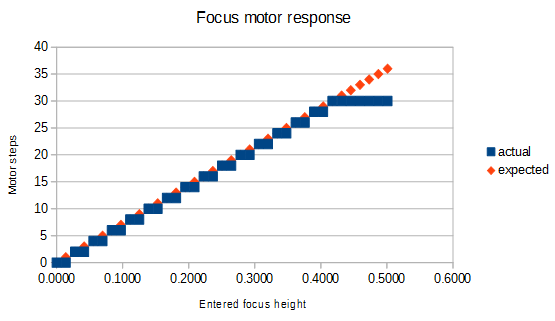
As Scott said that was just part of a discussion and was built from incorrect data. This is what the motor actually does.
It does nothing at all between 0.4" and 0.5", so it has a range of 0.4" where it can focus.
For engraving it’s generally fine to be a bit off. It’s cutting where you run into trouble. And they don’t officially support cutting anything over 1/4” thick.
They might not sell any PG more than 1/4" but they advertise “maximum Cut & Engrave height: 0.5″ (13mm)”
Work Area
Maximum material depth: 18" (455 mm) for Basic; unlimited for Pro
Maximum material width: 20″ (515 mm)
Cutting area: 11.5″ (290 mm) deep and 20″ (515 mm) wide
Maximum material height: 2″ (50mm)
Maximum material height with tray: 0.5″ (13mm)
Maximum Cut & Engrave height: 0.5″ (13mm)
Autofocus
Completely Internal — Lens moves internally up and down inside the head to focus on materials up to 0.5” (13mm) thick
Exquisitely precise — laser height measurement can measure the surface of the material to within 0.004 inches (0.1mm)
Multipass — Focus can be shifted between engrave passes, allowing detailed depth engraves.
Focus Override — the laser can be defocused to experiment with a range of techniques that require less intense heat
The camera does not move enough to focus on 0.5" material, it will focus 0.1" below the surface. And the fact it can measure height with an accuracy of 0.1mm is irrelevant when the focus moves in steps of 0.7mm .
I think a big concern has always been about having perfect focus for cutting. There has always been much todo about the material being absolutely flat.
However, the focal points the machine is capable of are limited to: 0.000, 0.028, 0.056, 0.083, 0.111, 0.139, 0.167, 0.195, 0.222, 0.250, 0.278, 0.306, 0.334, 0.361, 0.389, 0.417.
So, with only 10 focal points over the 1/4" cutting range, you can be as much as 0.014" out of focus. Per Dan’s response, this is within spec for the machine. It appears that focus may not be as super critical a factor as we thought.
I’m one of the first people that found the slightest bit of warp (0.01") could have a profound effect on ability to cut through. I tried to explain at the time that it wasn’t that a cut needed to be within 0.01" but that an additional error of 0.01" over what was used for the automatic settings could cause a problem. For example if the company assumed a range of 0.014" in focus accuracy for their settings to work, then adding another 0.01" to that could be a problem.
If the warp is where it takes the focus measurement then it could either make no difference or it could nudge it to the next setting which would be 0.028" higher.
Not disagreeing. Think I’m trying to say that if it ends up being the latter that may be outside the variance allowed for the automatic settings and cause an improper cut. They probably allow for a little due to the uncertainty of focus. But add the slightest warp, and it could be outside the range.
I could be remembering wrong, but I’m pretty sure they say somewhere that to cut up to 0.5" you have to cut 0.25" from both sides, i.e. you cut 0.25", flip the board and cut 0.25"
Still seems like poor design to have only 16 steps for what supposedly has high precision…
Exactly correct. Our system is designed with tolerances around step size, height measurement, lens variation, and many more factors. You can think of it as an error budget. Step size (which introduces rounding error), measurement variation (which, as noted in the specs, is small), lens variation, and so on take away from the budget. Allowable focus variation (which we’ve been discussing, and which is actually quite large) adds back. They balance closely. Then, the Proofgrade settings are configured to provide exactly enough leeway to balance the budget.
If your material is warped by 0.01", there’s a 50/50 chance it will make it better or worse as you follow the warp. (Note that it’s not the different height - it’s the change in height, so as you cut, part of the material’s at a different height than what the autofocuser measured). Should that change in height make it worse, it will fail to cut through.
It is both true that the material is exquisitely sensitive to height variation, and that the range in which material can be effectively “in focus” relative to the lens is quite large.
I don’t understand how that can be true. It seems to me the weakest link is the huge step size you use: 0.7mm. Why not stop on half steps instead of always doing an even number? Why is the hardware limited to half steps when it has a micro-stepping driver chip?
I think they set the power and speed to compensate for where the focus ends up. Let’s say they have a PG material at .121". They pick the focus height that is the closest, which according to dan leads to the material still being in focus. They then set the power and/or speed to just cut through - in effect compensating for loosy-goosiness of the range of focus. Since the power and/or speed is set to just cut through (in order to minimize char and kerf) then the ‘material is exquisitely sensitive to height variation’. And since they compensate through power and/or speed then ‘the range in which material can be effectively “in focus” relative to the lens is quite large’.
Although I’ve been following this thread loosely, I’m unclear if the claimed area of out of focus will appear on the lens side (Print head) of the work, or on the bed side of the workpiece. From what I gather the area is on the lens (Print Head) side?
Yes the top 0.1". If you enter a number between 0 and 0.4" the motor moves to the corresponding position. How accurate that is to the top of the crumb tray I don’t know because it depends on the homing procedure. But focus distances above 0.417 do not move any further. Previously the software limit was 11mm (0.433") but it was changed recently to 0.5" and the shipping details claim the focus range is 0.5".
Done?
The material rests on a 18” x 20” working bed. The printable area is 11” x 19.5”. The
maximum thickness of material with tray installed is 0.5”; the maximum thickness of
material with the tray removed is 2”. The focus range is 0.5”.
All that was “done” was to change the input limit.
If one could flip over the material being laser cut and then cut from the other side, then that might work. I have no idea how difficult or if even possible that is to do. My GF has been sitting in a box for about a month or so. I’ve been busy with work and redoing the shop space on my garage to accommodate a better workflow and isolate my mess from my family’s mess.
If I would have to guess I’d say it has to do with the current limitations of the camera-dependent height measurements. since the GF estimates the height by snapping a picture of the 45degrees laser projection, which is imho an unreliable and inconsistent method, the software sacrifices precision in lieu of repeatability by rounding to the nearest full step. and it doesnt revert to half-steps when not using the height gauge i.e. when entering the material height manually.
Well they claim the height measurement is accurate to 0.1mm although that is hard to believe after seeing the picture that gets sent to the cloud. Perhaps that is also a lie.
Perhaps but Scott’s golden email said his machine had 0.5" focal range but it doesn’t. So I doubt they have changed the head since then. How they managed to come up short on all three axes I don’t know.
Why not stop on half steps instead of always doing an even number? Why is the hardware limited to half steps when it has a micro-stepping driver chip?
If the “in focus” range is larger than one step height, then half steps wouldn’t much improve things, other than perhaps giving a half-step model better “error range” in that the middle of focus would be more precisely at the measured height, rounding to a half step instead of a full step, on average giving you more distance in focus in case of warp.
Since “in focus” isn’t well defined, I’m not sure how to proceed with this line of thought, though. Any ideas?
What I think would certainly improve performance would be if they took multiple height measurements across the cut/engrave path, and used that to control focus height. Then any warp would tend to be detected and corrected for. For “nearly flat” material, I’d think a grid of measurements, such as what 3D printers with Z-probes do, would let you model the “flat” surface and correct for it. Since Laser really is 2D, the math is easier than the mesh calculations that 3D printers use, which rotate the object being printed in 3D space to correct for bed alignment, etc. Admittedly off topic, but it’s pretty amusing propping a Delta printer’s print bed at a 20 degree angle and watch it print a cube that’s tilted 20 degrees so that it’s still a cube flat on the print bed.
This wouldn’t be enough for truly non-flat surfaces (engraving curved laptops, etc.) but it’d help with gentle warping, or material that’s raised up due to some material on the crumb tray. And that’d give some percentage more reliable lasering!