Related to Discussion: 0.5" focus range not achievable

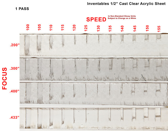
Here’s an experiment I did with 1/2" acrylic from Inventables. This was done in Oct 2017, before the software allowed .500" focus.

This is the inverse of the experiment I mentioned in the post above. Here, I am moving the focus from .300" below the surface of the material to .077" below.

But, the difference in .100" of focus change is very definitive, nonetheless.

What is difficult to see in this picture, but is there if you look closely, is the change in kerf. Look at the top cuts verse the bottom cuts.

I still have these pieces somewhere. I’ll see if I can get some better pictures of the changes to the kerf.

An interesting side note is that you can clearly see the over-burn at the start and stop of each cut when the laser is at full power before the head begins to move.

5 Likes

Assuming from discussions above, that a +/- 40% of beam diameter is an acceptable focus tolerance standard:
The Glowforge’s focused beam spot diameter of .008" (per Dan) would permit a spot size range of 0.0048" - 0.0112".

Assuming even more - that the collimated beam diameter is 0.250" (which Google assures me is pretty much standard), the focal range that gives us the acceptable tolerance is +/- 0.0264".

You can see that at the 0.083" mark (which seems to be the focus error at .500"), the spot size is a whopping 0.0180". An error of 125%.

To get within the suggested +/-40% to have the beam to be considered focused on .500" material at a focused height of 0.417", the collimated beam would need to be 0.085" in diameter.


(The numbers look much worse for GF if we expand the beam diameter, so I am giving them the benefit of the doubt.)

I really wish @dan would weigh in on this. Preferably with something other than “it is within specifications” or “we can’t disclose that because its super secret”.

If it isn’t capable of performing to the original specs, I certainly don’t think anyone is going to freak out. On the other hand, continuing to be misled if it doesn’t…

(Can you tell I really want to understand this?)

EDITED TO ADD:
Here’s the full view of the scaled drawing above, for perspective:

4 Likes

thanks again…
question: if you believe the acceptable range is only 40%± of 0.008", how would you explain the many successful “prints” on warped material, or curved surfaces? such as this one, where the user assumed continuous autofocus was already implemented:

and many more, including ipads, rat’s skulls (!!!) etc…
(which brings up the point that the term “acceptable” is definitely up to interpretation…)

the fact that the failure of many “prints” have been attributed to warped material might have to do with a weakness in the 1-point autofocus system, which - since as you explained uses the camera to estimate distance- might grossly miscalculate distance because of parallax -compounded displacement (again, I don’t yet have a GF, so I have not seen it work)

1 Like

That’s not my number. That was suggested by another member further up in the thread as a figure that was apparently discussed previously in other threads.

Certainly the laser will still burn stuff when it is not precisely focused. That’s not what this thread has been about.

This discussion has been about the specified ‘precision’ focus range that it is sold as having, and whether or not the unit is actually capable of it.

It has also been about the practice of letting users set a focal height that the unit apparently cannot achieve, that some feel is a deceptive practice.

Imagine if Ford sold a car that they advertised as having a top speed of 70 MPH, but only was capable of achieving 55 MPH. When it reached 55 MPH and you kept pressing harder on the gas, it didn’t go any faster but the speedometer kept increasing saying you were.

When you asked a direct question calling out the fact that the car doesn’t quite go that fast, they dismissively respond by telling you “the vehicle is fully capable of highway speeds.”

Sure, the car still ‘works’, 55 MPH is a highway speed, and it still gets you where your going.

But, it certainly isn’t performing up to the specifications that they claimed (as any reasonable person would understand from reading them).

Displaying a fake speed on the speedometer to make you think it does perform properly would be deceptive, right?

10 Likes

Thanks @scott.wiederhold, @palmercr. I always enjoy these tech discussions, and I look forward to any official response.

3 Likes

well…except that speedometers do lie. It is known!

2 Likes

It is illegal in a Germany to sell a car with a speedo that reads higher than the car is going. So they reduce the speed displayed by a lot. About 4mph at 60.

1 Like

So VW just extended that philosophy to their emissions readings? :slight_smile:

8 Likes

I’m pretty sure what they did was illegal.

Could you let me know what question you’re wondering about? There’s a lot in this thread and I’m not sure I follow what you’re asking.

Also: if you have questions, Problems & Support are the best (and only) place to be sure they’re addressed - Beyond the Manual is the only section of the forum that staff do not read regularly (including me), and I never check my tags.

The question is “why does GF claim to have a 0.5” focal range when the lens only moves 0.4"?

The problem was reported to support: 0.5" focus range not achievable and they claimed black was white.

The machine isn’t physically capable of focusing at 0.5" and it doesn’t position the lens any differently for settings between 0.4" and 0.5". So for 0.5" materials it must be 0.1" out of focus.

1 Like

Well, the general gist is about the focus range capability.

It is advertised as having a focal range of 0.5". However, through examination and experimentation, it seems to be significantly less.

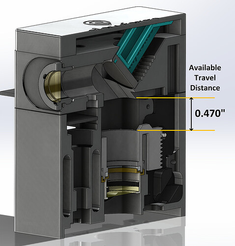
The first limitation appears to be physical. Measuring the difference between the physical travel extremes results in roughly 0.470". It seems the head assembly has physical limitations preventing a full travel distance of .500" (and certainly much more room would be needed to overcome tolerance build ups if an accurate calibration is desired).


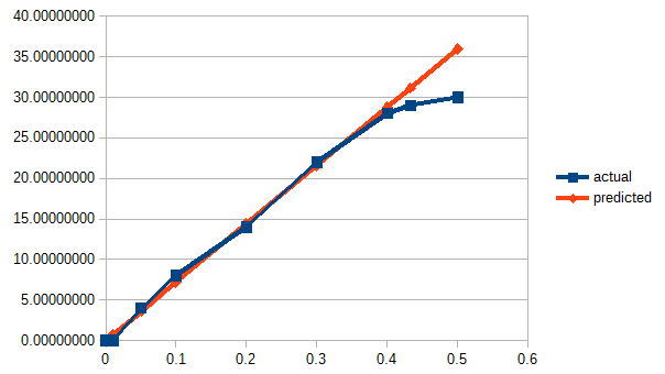
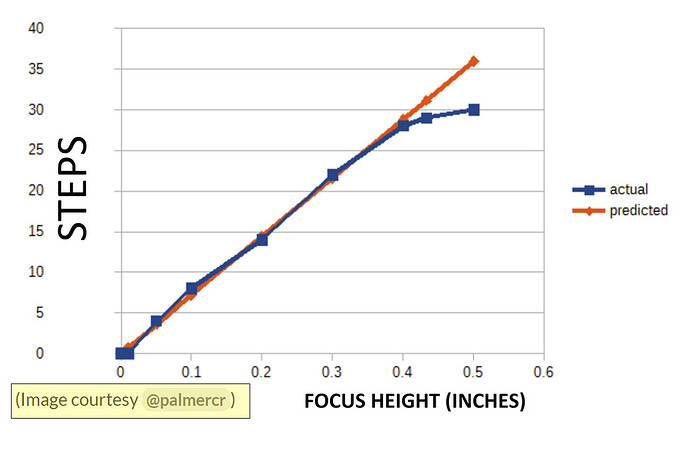
The second limitation appears to be in software. The number of steps sent in the file to the unit for the focus stepper never exceed 30. When the focus point is ~0.000, the number of steps is 0. At 0.500", it is 30. The stepper motor, combined with the gearing, is capable of advancing the lens in 0.0139" increments. This means the lens never moves more than 0.417".

Furthermore, the number of steps is proportional to the expected focus, until it reaches just under 0.400", then it slopes drastically. This is illustrated here:

image
(Image courtesy @palmercr)

The question: Is the stated claim of a focal range of 0.5" accurate when the device appears to only be capable of a range of 0.417".

4 Likes

Where are the units on your axes man! And what’s with the 8 zeros after the decimal point on what should just be integers?! :slightly_smiling_face:

4 Likes

Whoa, whoa! Please note the image credit. :wink:

(He sent it as part of an informal chat between us, so pretty wasn’t as important as functional.)

I cleaned it up a bit:

3 Likes

Regarding the second half of your question, we don’t guarantee any particular range of motion, and in fact there’s some variation on maximum physical travel from head to head. We mistakenly put a specific range of motion on the website before, then realized the error and corrected it.

Regarding the first half, the focal point of a lens is infinitesimally small; any optical system “in focus” will necessarily have some distance between the focal point and the surface. I don’t know of any universal quantitative definition of “in focus” across all optical systems; it typically means “close enough to the focal point that the desired goal can be achieved” - for example, an in-focus picture is one where bluriness isn’t noticeable, or is below a certain wavelength, or grain size, or somesuch.

Interlude: just checked Wikipedia to make sure I wasn’t too far off base. It says:

An image, or image point or region, is in focus if light from object points is converged almost as much as possible in the image, and out of focus if light is not well converged. The border between these is sometimes defined using a circle of confusion criterion.

It seems to agree that the definition is subjective, although it doesn’t propose a functional test.

In any case, the Glowforge lens can move sufficiently to place that focal point close enough to the surface of material to cut (up to 0.25") or engrave (up to 0.5"). Since it can focus sufficiently to accomplish its goal - yes.

For those curious about history, we first designed it so it can engrave 0.5" materials; then later, wrote the website copy as best we could to convey that, as well as address questions like “well, can I engrave over the full 2” height of a 2" tall object?". As always, our goal is to try and convey the best information possible to the largest number of people, and we may occasionally fall short. We did initially (with range of motion) but I think the current language is accurate and leads people to the correct conclusion.

I think this was a practical question about what you can do with your Glowforge, which I’m happy to do my best to answer. In the unlikely event that folks want to use this as an opportunity to debate the definition of technical terms, I will respectfully allow them to do so without interrupting. :slight_smile:

20 Likes

Thank you for the response, @dan. That’s an answer I can live with.

In this forum?

16 Likes

First up I think we ought to define “term” and “definition”… :smile:

6 Likes

Before we go defining things, shouldn’t we define what “define” means?

2 Likes

What does “mean” mean?

2 Likes

I think it’s like an average or something.

5 Likes