Haha–beat me to it! Either you type faster than me or I’m too distracted by this cat laying across the backs of my legs.
3 Likes
Sitting here weeding. Five more minutes. One hour of total weeding on this project. Gorilla tape would work but is actually slower and I’d use a whole roll!
3 Likes
I’m certainly not complaining, just trying to understand what to expect. I still don’t understand what you mean by changing the score lines to engraves. I recall you saying something about my strokes being very small. I understand making the stroke larger for an engrave, but did you change the file type? Why outline the stroke?
Oops, I probably confused you there–the original file you sent had such thin scores (I think they were about 0.02pt) that I couldn’t see the figures, so I thickened them up a bit when I worked with the file in Illustrator. That is a different issue that had no bearing on how they worked in the laser interface.
I’m not sure what design software you are using, but if it’s Illustrator, in order to convert a score line to an engrave line, you need to convert that line to a closed figure. Think of it as a straight line that is converted to a very thin rectangle. The way I do that in Illustrator is to change the stroke of the line to whatever I want the thickness of the engrave to be (in this case it was 0.5 pt), then choose Path > Outline Stroke. This command converts your stroked line to a filled object (with stroke of none) with the fill color the same as the original stroke color. I hope all this makes sense.
The file type was still saved as an SVG for the Glowforge interface.
Edit: I just realized that I did not make it clear that the Glowforge interface doesn’t care what the stroke thickness is, which behavior may be different from what you are used to seeing in the lasers you are currently using. You could send two lines with very different stroke widths and they would both be interpreted the same, as a cut line. The way you specify different operations in the GFUI is by color, not by layer or stroke width.
3 Likes
One hour of weeding? Holy smokes! What have you gotten yourself into?
2 Likes
When we have low-power mode available, I’ll use scoring even more. In it’s current incarnation, I prefer it for long, straight applications. The 15-min lines on the dial fit the bill. Looking at the back of the piece, the beginning and end of each score had a tiny pin-prick burn through at minimum available “laserness” - 1% & 197 in/min.
Here’s an example from the sundial:
The vector file I used had a wider stroke set for the hour lines, but stroke width of vectors is ignored in all cuts and scores (the beamwidth is fixed). Had I opted for engrave, the wider hour lines would have appeared as designed, but at a “cost” of a vastly longer engrave time – that would have taken 3-4x longer to raster the entire design.
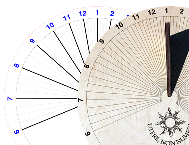
Sharp-eyed readers will see that I added the decoration and motto after the fact.
9 Likes
You could change the hour lines to be very narrow rectangles. I believe that’s what they did on the Founder Ruler. It’d be interesting to see what impact engraving those and scoring the rest would have on the overall time. I’ve seen some pretty efficient engraving algorithms appear to be followed by the GF.
Sure – I knew how, just forgot to do so. Might be a useful example to others in the meantime…
1 Like
Who’s right here? @dwardio is suggesting what I’m used to. I’m also not used to the whole cut/engrave terminology. I’m used to vector/raster. So, for the purposes of continuing, I’ll use vector (doesn’t see stroke width)/raster (sees stroke width and fills).
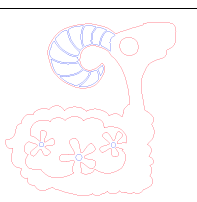
My deer toy is exclusively vector lines. There are no fills. The lines I want cut are red 255 and the lines I want engraved are blue 255. If I want to vector cut my toy on the FSL at school, I set the red lines to high power/low speed and the blue lines to high speed/low power. This is what I’ve come to know as scoring in GF speak.
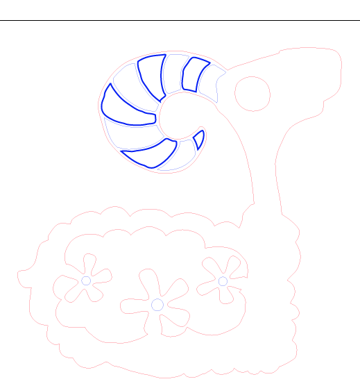
If I had varying stroke widths like pictured above, I would need to raster (engrave in GF speak) the blue lines. I would expect it to come out just like the images appears (provided my strokes are thick enough to see). Yes, it would take longer because of the back and forth motion of the laser.
I understand that the power may be too high to score my toy on both front and back without cutting through at this time, but I expect the GF to be able to see my vector lines in both the scoring and engraving functions without having to change the file. Do I really have to change all my lines into shapes in order to engrave/raster?
4 Likes
This is decided by color. So you have 2 colors here. You’d tell your Glowforge to Engrave your blue. And you’d tell it to either Cut or Score your red. If you want to cut one part and score another, they need to be different colors.
NOTE: I’m new to this! So I might be wrong!
I’m 99.7% sure I know what you want and how you’re saying it is clear to me. If you’ll PM me your .ai or .svg file, I can answer with 100% certainty.
The short answer is yes. You will have to change any lines that you want engraved wider than a score line, to closed figures. The GF software does not work like the FS software you are used to. If you want the lines simply scored as you describe above, in the GFUI you change the blue lines from cut (where lines default to) to score. If you want the lines wider than a standard score you will have to change them to fills. If you import a wide stroked line into the GFUI it will still be interpreted as a cut (or score) line. If you change that cut or score line to an engrave (the software will let you do that, oddly), it does nothing–neither cut nor score nor engrave.
2 Likes
This conversation is incredibly useful, learning a lot here… it does not work the way I would have expected. So much more to learn. Thanks all.
I have a possible alternative to the rasterized engrave you are describing, but first let me clarify my understanding of how GF would treat this case.
Let’s say I had a line which was set to have a stroke width and I convert that to an outline path, or just have a long narrow rectangle. And this line is at a 45 degree angle. And I say to engrave.
GF will, if I understand correctly, treat this as a raster engrave with the rasters being parallel to the gantry and thus very short line segments across the narrow dimension of the shape. Thus the head will vibrate back and forth rapidly. Though if there are two of these separated by space, it may treat the combination as a single engrave sending the head back and forth over this whole are but turning the laser on only for the few pixels of the thick lines.
Alternatively, GF could treat it as an “engrave” at an angle and make the “rasters” parallel to the long side of the line shape.
Assuming that the second option is not what GF does, one could author the thickened line as a series of paths, each a beam width apart at very low power (now that low power is available).
Thus a “thick line” would only take the cost of five or ten (light) scores vs the time cost of a rasterized engrave. And would be a manual way of achieving the second option above. It would seem that macros could be written to generate the vectors for these fat lines.
1 Like
I guess in theory it’s possible to generate code to do the parallel scores. Betting it’s just a lot, lot more difficult than it might seem. But that aside, a score is most often not a straight line on one axis. Think circle or polygon or just thick fractal lines. So you are dealing with two axis. Depending on the speed of the head and gantry the accuracy will suffer. It’s possible to have a slight amount of ringing when turning corners at the highest stroke speeds. Given the apparent difficulty they had working the accuracy of the single axis engrave, a two axis engrave like score might not be something simple.
The easiest alternative in the hypothetical you describe is for the designer to rotate the design on the page through 45° so that the lines to be engraved are actually running horizontally on the artboard.
(I do do that sometimes - run the longest of the thin engraved rectangles along the X axis to cut down on processing time.)
Doesn’t work if you are trying to run the grain in a specific direction though. I guess you could also rotate the material if the design was small enough. 
1 Like
I was describing the simple case of just one, but complex thick-line art that is still mostly open space could benefit from this.
At least in theory
1 Like
Agree.
(And the rotation to put the majority of the engraving along the X-axis works too, to cut down processing time. It’s just an easy alternative that doesn’t involve recoding.)
It helps if folks are aware of it though… most folks haven’t had a chance to play with this yet, but I always orient the bulk of the engraving along the X axis if the grain pattern allows it.
Call it a free tip in advance of the machine arrival.

3 Likes