Six digit 7 segment Clock

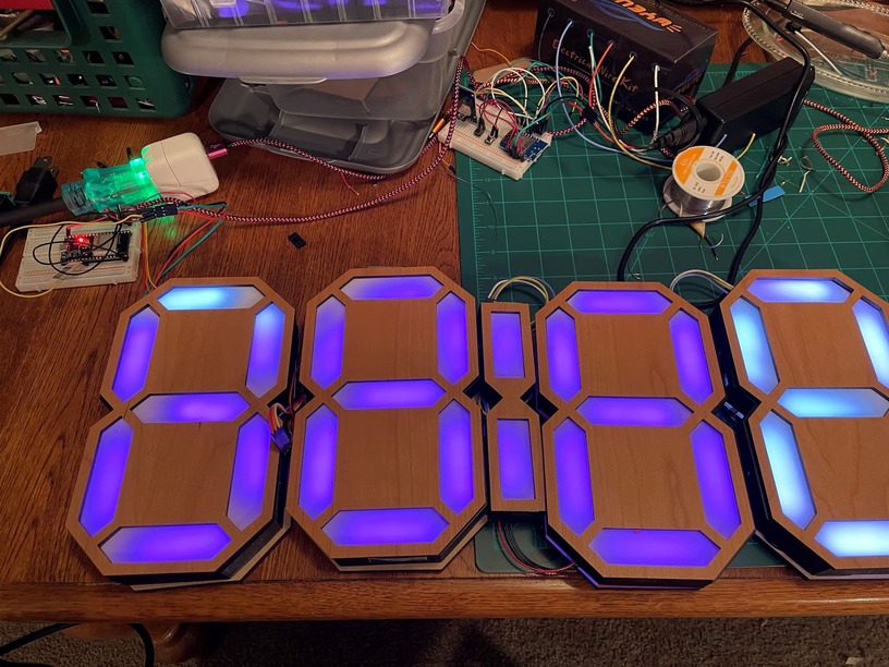
I have been inspired by Ivan Miranda and many others. I figured I would do the word clocks like @ben1 does, (whoops. I mean @mark14) which use LED matrixes, but ended up getting strip LEDs first to figure it out. I started out with four digits and was so happy with them that I made two more.

It was a great experience. Learned a few trick in Onshape. Got my maker card punched a couple times like first perf board circuit, first time using a circuit design software, KiCad. First time using ws2812b LEDs. First time using ESP 8266s (before had used ESP32s). The most libraries loaded to the Arduino environment. First time frying a microcontroller. First time de-soldering a board. First time using an RTC and switches to control a program other than blinking a light. Got to learn about WLED to control the individually addressable LEDs. Wow. It’s an amazing program and easy to use. First time using a logic level shifter (although ended up not needing it for this run). Already thinking of version 2.0 which would get dimensioned to use Proofgrade better and not use 3D printed parts, so all laser cut.

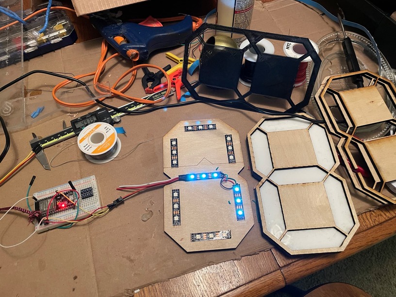
I love Onshape and Kiri:Moto. It makes these project so much easier. Started with a test piece to see how the white acrylic I have would work and how bright the LEDs would be. Also to see how I big the sections would be. You can make a 7 segment with all the same lenses, but there are models that have a couple different shapes which make the digits a bit easier to distinguish.

One of the goals was to make it as easy to make as possible. I could have 3D printed the letter housings, but that would take a lot longer. I have found a happy medium in printing sides with the 3D printer and bases and tops with the laser. I used cardboard to prototype.

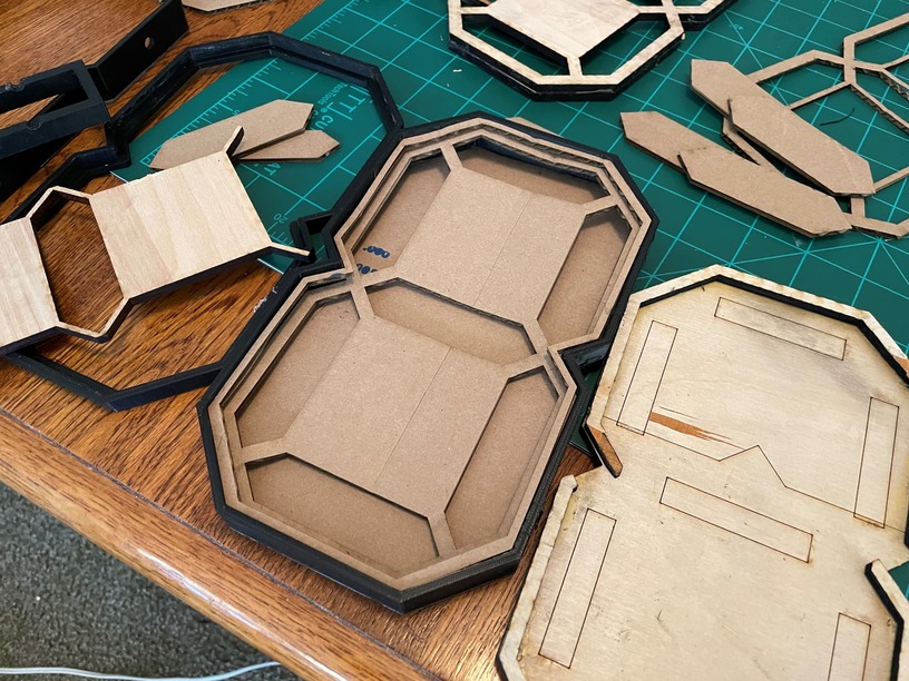
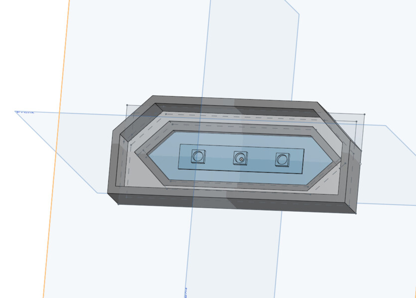
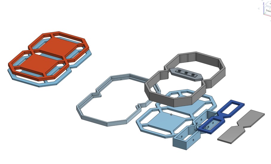
Several layers were needed. The top layer to trap the lenses. A second layer to align the lenses. and then a third layer to isolate the lenses so that there is minimum bleed from segment to segment. Then a bottom layer for the LEDs and the back. Next version will add one more layer in the middle for the LEDs and then move the wiring to the back of that layer. The conundrum is encountered. If the LEDs are on the back layer, how does one attach them to the side of each digit and then join them with a three prong dupont connector?

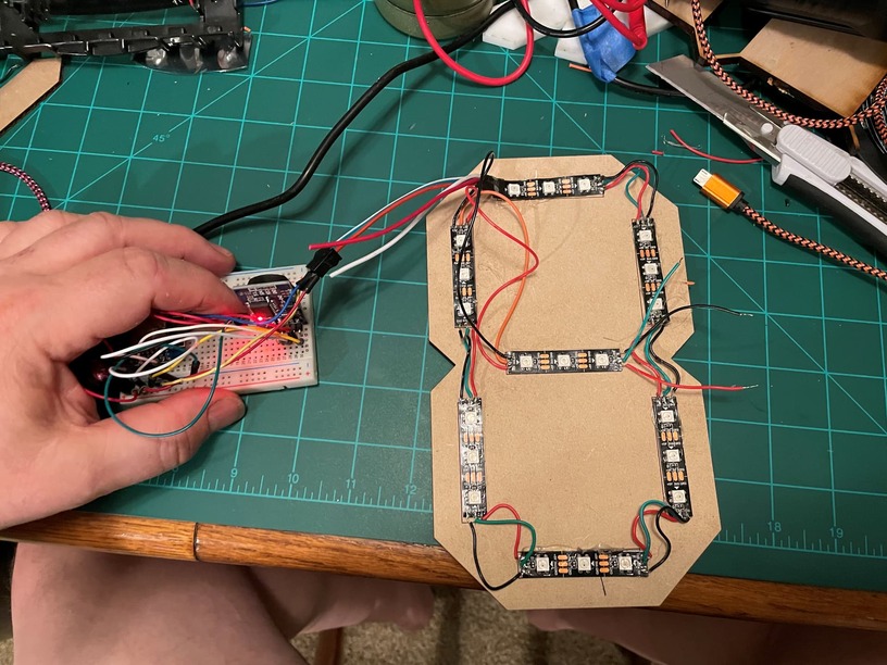
One of the decisions I had to make was how to join each digit. I had a box of dupont connectors and a crimper and had the wire on hand. I’m still learning.

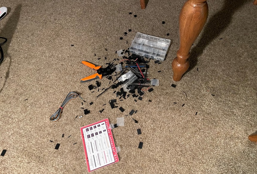
I don’t have a proper workbench at the moment. I use the dining room table. Things fall on the floor all the time. I would like to talk to a watch maker and learn some techniques on how to handle dropped items: tools and parts. It’s maddening.

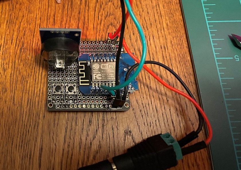
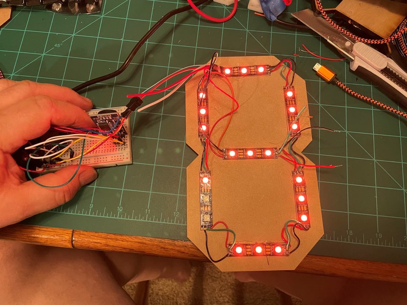
The WLED control environment is absolutely amazing. It was good to test the digits as I made them before I had enough to run the clock and get the clock controller set up. Once I got to four working digits, I started on the clock controller. I am so indebted to all the folks who freely share their code.

The code worked right off the bat once I figured out the pinout for a D1 mini controller.

So I added two more digits. It was working great. That’s when I started transitioning from the breadboard to the perf board. First time. I spent a while getting the circuit down and did some one on KiCAD for designing the board. Lots to learn there, but at least I got my feet wet. It drives me nuts that all these guys shell JLPCB and the like for making boards for cheap. Sure, easy for you to say. You actually know how to design a board that works.

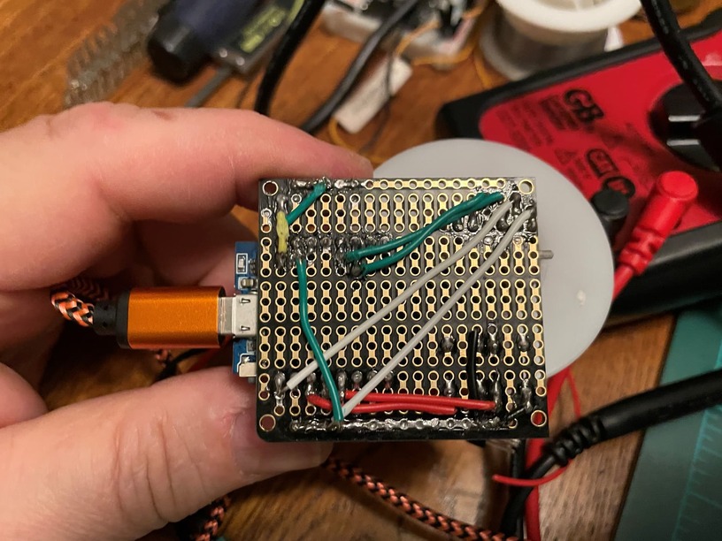
It may not be the prettiest, but it’s mine and it worked. Well, first time it didn’t. Forgot the main ground to the microcontroller. Easy enough to fix.

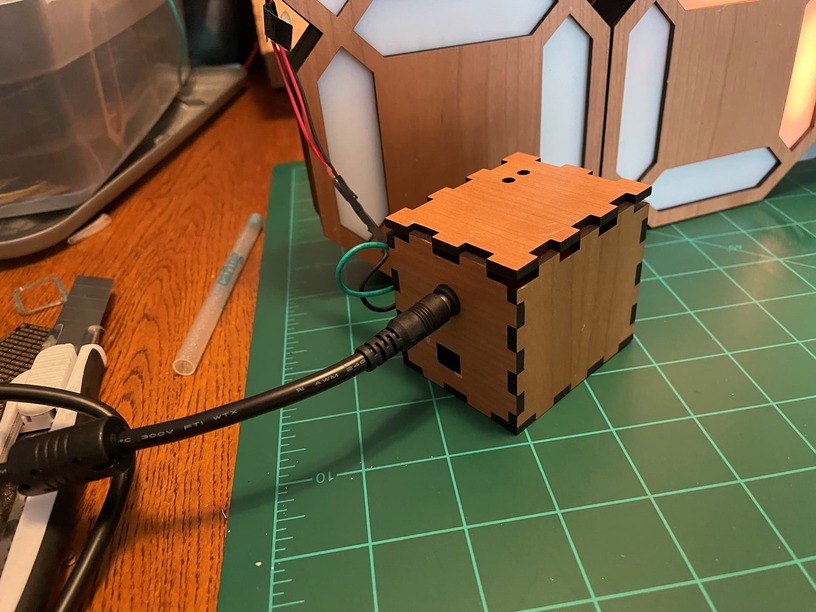
So I went on to making the control box. Used the Glowforge for the enclosure and 3D printer for a base.

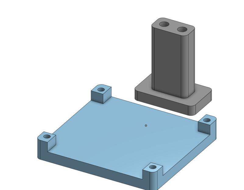
The silo looking things are for guiding some type of pin/rod down to actuate the push bottons . It’s sized for a ballpoint pen ink canula. Used some threaded inserts for the base which work great. Hot glue to fix everything else.

So everything was working perfectly. Just needed to put some glue for the backs to set them first and hook up the project box. Whoops. Something was in backwards. No magic smoke but I did fry the D1 mini.

I had a conundrum. I had extra for all the parts except the real time controller. Do I try to desolder the D1 mini and use the the old board, or start from scratch? So I ordered solder wick and a solder sucker. Was not able to detach the D1 mini, but I did manage to free the RTC. In the meanwhile I got three more RTCs so I can make a word clock or two and another 7 segment,

So a few days of waiting. Did the final connection and put some hot glue where needed and shrink tube as necessary. I am very pleased with this project. I do think I’ll make the next version so that it is all laser cut though.


I used Proofgrade Cherry medium plywood for the faces. Used thick Draftboard for the lens brackets and back of the digits. Used some 6mm white opaque chemcast for the lenses.

Joined the digits together with small nuts and bolts through the sides.

By the way, I love my Glowforge. It works as I need it. I can’t imagine not having one.

Another personal note. I was the athletic director for a high school once upon a time. We needed a new scoreboard because our gym scoreboard didn’t have all the necessary feature. I had to hustle some sponsorships to come up with $8,000 for a board that used incandescent mini bulbs that we had to replace a few regularly before games. Of course it drives me nuts to think that with a bit of help, we could make a good scoreboard for much less these days.

51 Likes

Beautiful job on a very useful project.

6 Likes

I am so impressed!! What a journey - thanks for sharing the adventure with us.

10 Likes

I have been trying so hard to figure out a mechanical segment device, but I love what you have done here! Thanks so much for sharing your story and journey.

9 Likes

You might find veroboard (aka stripboard) easy to work with. In general it makes designing and soldering relatively simple circuits like this a lot easier and cleaner. They work a bit like breadboards and are really easy to design for (I used graph paper to mark connections at first and then graduated to Dia, a simple free diagramming program that worked pretty well for making snapped connections between points. )

My progression was breadboard to freeform protoboard like yours to stripboard to learning eaglecad and getting custom boards printed. It was a pretty natural path to follow, I think.

8 Likes

I don’t know why I ordered this board instead of the veroboard. I think it came up first in Amazon in my search and it looked very neat and sized for the projects I was thinking of.

4 Likes

Have you seen Ron Walter’s videos lately on a servo driven seven segment? He’s a fellow Missourian.

2 Likes

There are excellent flip dot style 7segments out there, they’re just painfully expensive.

2 Likes

Thanks for the detailed write-up! Looks like it was a fantastic journey.

7 Likes

Of all the things you described…of all the processes that you required…of all the materials that you used…all of which were over my head, it boiled down to this for me about you and your clock. I think it’s wonderful.

11 Likes

Terrific work! All these things need lots of “Stick-To-It-iveness” . The journey is very important!

10 Likes

That is amazing.

6 Likes

Amen to all that @Xabbess said! It runs far beyond my ability to follow though I was thinking you had a 3d printer that could handle complicated back-end parts.

Diamond setters have a much more expensive issue than watchmakers. I was aware of a major jeweler that had a thick white rug under the diamond setter’s workbench that was replaced after many years. There was such a commotion of folk wanting to mine it for diamonds and gold that the company had to have special security to get it to the trash.

Working with tiny screws you have an easier time as they are magnetic. The flyers that harbor freight puts out usually have a free coupon for the magnetic dish that they sell. Also, a foldable bench, with gutters would have good use and tray/shelves with shielded magnets underneath to store and arrange those things that are magnetic. I had a set of tiny drawers with many types of fasteners that fell and are now in a pile mixed up together. Collecting them out of a rug with a big magnet was easier than separating them by type.
Of course, not everything is magnetic but for those that are magnets are great and the rest easier to deal with for not mixing with the magnetic stuff.

5 Likes

The flashlight trick is very useful. Here’s a random youtube video of the idea:

8 Likes

Really amazing work and writeup!

7 Likes

I think you may have me confused with another Ben. I haven’t made these before!

Good job though!

I have found that when building PCBs it is a lot easier to design digitally and then have the PCB made by OSHPark. You get the chance to really optimize the design, add mounting holes, and use both through hole and SMT components. The only hard part is waiting for the boards to arrive.

5 Likes

We don’t drop things. My workbench is set up to keep movements small and things secure from being pushed off the edge. Every work surface has a lip to prevent something sliding or rolling off. All parts go in specific-use compartmentalized trays. Tools aren’t left on the work surface, they’re used and put back in place. If needed two minutes later they’re taken back out. Tools are stored in order of frequency of use so I’m not opening & closing drawers willy nilly. Repair parts aren’t high use so they’re removed from their drawers (lower ones) when needed. All the parts for a repair are in a special tray for that watch & dropped into the tray in order & the tray rotated as major assemblies are disassembled. Trays are wide & shallow so they’re not tippy.

Physical motions are limited. For instance the watch is mounted on a holder that keeps it in place. When I remove a screw or spring or plate it’s raised about an inch or so over the watch and moved away from me toward the back of the bench about 4 inches and then lowered into the tray. Parts are placed in the tray, not dropped. So a part travels 2" up, 4" back and 4" down. All of which can be done without moving my arm from where it’s resting on the work surface. Watchmakers & repairers are a study in the conservation of motion.

The parts are tiny, will get contaminated if dropped on a surface that’s not been cleaned for them and are very fragile - a drop to the floor is often enough to warp or damage something like a watch hand. On a repair you often can’t buy a replacement part so you do your best to not lose them due to clumsiness. Otherwise you’re going to be spending a really long time making replacement pieces.

Now in the garage I drop things all the time :sweat_smile:

13 Likes

That’s what we call a jeweler’s prayer meeting. Where everybody is on their hands and knees. You’d fit right in.

I love how you combine 3D printing and laser cutting all the time!

9 Likes

Indeed and I find myself using it a lot even on rugs when the object is big enough or light enough to not make it through the piles. I have a plastic disk made for the microwave that had a quarter-inch piece above it and from Skycraft some metal stands to put a laptop on that end up with both a gutter and wall when upside down. But mostly I depend on strong magnets, as stuff tends to run off and hide in corners and the magnet can search a very large area compared to even the flashlight. For tiny pieces of wood or plastic, the flashlight or even tape like for masking will hold something very light. :upside_down_face:

2 Likes

I’ve used this flashligh method a lot. Guess I must drop stuff a lot.

2 Likes