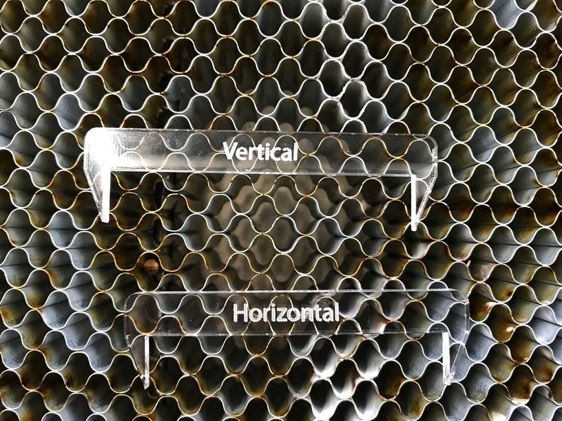
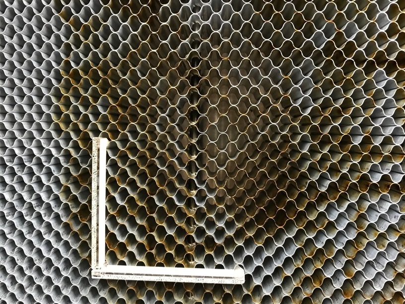
So working on the alignment issue, and this is part one of the project was just to have some spikes that you can shove into the grid (and yes, before all the CNC Milling folks jump on this post, yeah, I get that the grid is not locked down - that’s why this is part one - part two will be locking a structure to the case under compression with these spikes into the grid holding everything in place rigidly).
The major reason was figuring out a nice tight set of spikes to go into the grid, which will eventually be a full 3D thing that goes against the case and locks down the grid and provides a nice repeatable place to put your work in general.
Now the horizontal doesn’t grip as well as the vertical (which is quite solid) since the horizontal grid pattern actually is kind of weird if you look close, this is not a perfect honeycomb and there is a slight offset between rows). The vertical locks in sharply. Need to play some more with that.
I’m glad you’re working on something like that. It was one of the things that I’ve been interested in because once the “ooh, I have a laser!” thing wears off a bit I’ll want something repeatable. I’ve held off thinking about it too much since I haven’t had a unit to evaluate.
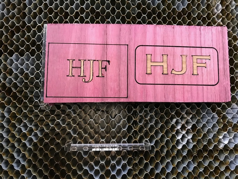
Great idea! I’ve been struggling all day with aligning objects so that engravings are square (posting examples soon). Even having the vertical guide locked in would be a huge help. Was going a different direction entirely, but this is a simple, elegant approach.
OK V1.1 is printed, does pretty well, but off by maybe .25-.5mm or so (wouldn’t fit if glued. Once I have the distance right, then a top cap (to the outside) as suggested by @tom) will be coming to make it square and have the tabs to go to the case…
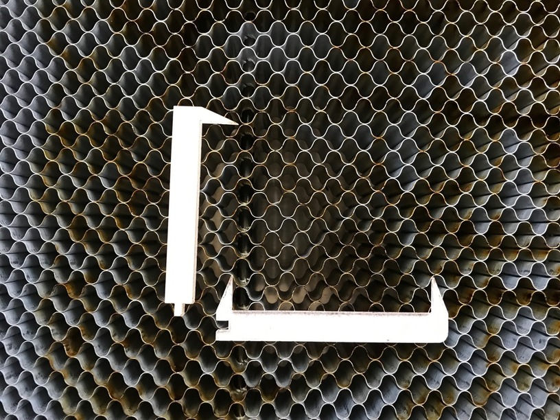
An idea: you could cut the right angle out of one piece and glue the spikes in as separate pieces. Thin (in Z) stops are nice and cutting the angle out of one piece will give you more rigidity.
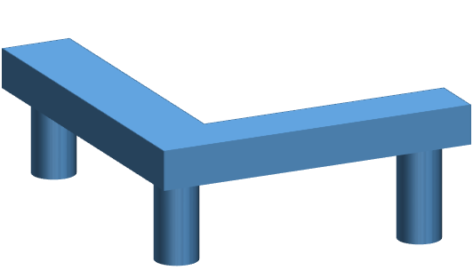
What would be your thoughts on something like this where you have an “L” shaped cut out, and you put cut three holes in and glue in three dowels. Would this work or am I missing something?
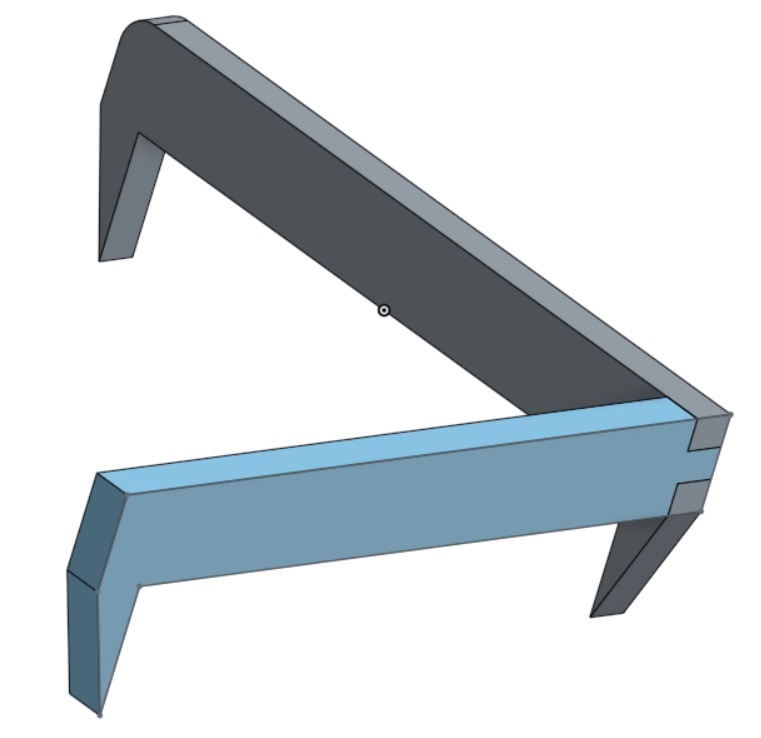
(Not looking to impress anyone but don’t forget that you can do some pretty quick work in PowerPoint for mocking up designs by using the 3D Rotation feature!)
I like your ingenuity but are there not better ways to create a square edge? I mean are there not some other permanent elements against which to butt up?
And, while I know this is not what you’re trying to solve, the big problem with the GF is that, even if we are able to establish a known perpendicular zero point by hook or by crook, the software has no idea where that is.
I am really looking forward to seeing a post from GF confirming that there is a solid solution to this issue.
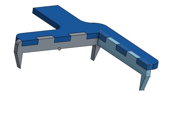
It is essentially that shape as you will see in V2 which will have the plate on top giving the connection to the case via the long tabs (this is not a finished item).
Powerpoint doesn’t have the precision (the tolerances here are 0.25mm) and since OnShape gives instant 3D preview no need to use something else.
They are actually really, really hard to get to (hence all the ingenuity you refer to) as the only “easy” part of the case is behind the side rails of the y-axis, so the challenge is getting to the sides without interfering with Y-axis movement. Once I have that we will have absolute positioning and the honeycomb will be held in place by the 4 brackets allowing us to have known measurements (which may require some correction factor of course)
You are somewhat incorrect in that the machine does have the ability to position stuff absolutely, remember if you make your SVG 12x20" it uses absolute positioning, so you can “measure” the offset to my holders and then use that in your calculations (just like on my 3D printer or CNC mill the absolute 0,0 is a soft set thing as well)