Tutorial: How to cut without the Crumb Tray (Honeycomb)

That might be easier for some folks to use, thanks for sharing it! :slightly_smiling_face:

2 Likes

I get 1.35" for the tray height. If you pull the tray out and measure the plastic sides (which it sits on… not the legs that go down in the notch), and then subtract the little lip height between the side and the honeycomb, I got 1.35".
Somewhat minor difference, I’m not sure how much it matters.

VERY minor, indeed. :wink:

I’m new and just got my Glowforge. Let me get this right…even without the crumb tray, the top of the material needs to be in the 1/2" zone between where the honeycomb tray sets and the laser head? Therefore, I cannot enter a material thickness with a negative number to set the height of the material if the crumb tray isn’t in place? Instead, I would need to build up the material with another object to get it to this zone? I just want to make sure that I understand. Thanks in advance… Matt

5 Likes

Correct on all counts. :slightly_smiling_face:

2 Likes

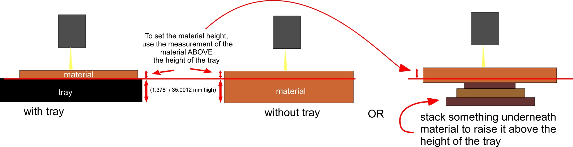
Here’s a look at it. :slight_smile:

26 Likes

Just to explain why - the beam focuses at a specific distance from the lens. To achieve focus for materials of varying heights, the mechanism in the head moves the lens up and down. The crumbtray surface is basically the zero mark - below that spot, the beam can no longer be in focus.

4 Likes

Thanks so much for this! Used it twice and got a perfect cut right out the gate! I’m terrible at math and Excel, so I never would have been able to work this out on my own. Much appreciated!

1 Like

It looks like it’s been a little while since this tutorial was written and some improvements were slotted for the GUI. If the material is raised so that the surface is in the 1/2" zone above the honeycomb, is it still necessary to do these precise measurements and enter in the adjusted material thickness into the UI to get accurate alignment between the camera and the material surface?

1 Like

For now, yes. :slightly_smiling_face:

2 Likes

thanks for the update!

1 Like

Well even if the GF would do it itself, for safety you need to make sure you are clear of the nozzle so you don’t hang up on the head.

3 Likes

Thanks so much, graham. Are you able to define each of the terms on the calculator you invented? I’m engraving a clear plate, so the plate itself is 1/8"thick, but the height of the plate when turned upside down is 3/4" (this includes the empty space underneath the pate when turned upside down), so the plate itself isn’t thick, but it is “tall.” Hence, I don’tknow what to putin thecalculator for the thickness questions. And I also don’t know what the"desired new height above the tray"is or how to get that info.

2 Likes

Question. I know this thread is from a few months ago. Newbie here. Wouldn’t it be easier without all those calculations and measuring, to take the crumb tray out and place on a level surface. Then put whatever material you want to engrave and place it right next to the crumbtray. Put shims or materials under your material and make sure you measure against the crumbtray to make sure the top is somewhere in that 1/2 inch zone you have to be in? Just asking… Newbie here.

5 Likes

Great question! Yes, you could certainly measure against the crumb tray. (The thread is very old… when it was written, we did not have the Set Focus function, and had to do it with math.)

6 Likes

Jules is right (as always :stuck_out_tongue: ) and the set focus has made some of the old tray info a bit outdated. The set focus feature made tray calculations really easy and all you have to do is get the material somewhere in the right height range and the GF will do the rest.

6 Likes

Yeah, so while you don’t need the math like we old timers used to, you do need a rough guesstimate to get the material in the focal range. (and to figure out how much stuff to pile underneath to do so.)

7 Likes

I have the same lino stamp blocks from inventibles. I tried using them then realized the height was too much for the GF. Have you figured out a template or shallower bed covering that would allow for a cardboard template to be cut to hold those blocks in place so you could position designs and center them.
I was also wondering about the settings.
I scanned these amazing antique wood blocks with the idea of reproducing them sadly the gfui did not allow for any serious editing of scanned items when I scanned them. I wanted to add a line of simple text which seamed impossible.

If you’re generally happy with the scan results (I just use a scanner for most things now as the GF doesn’t do a great scan to begin with), you should be able to create a separate file with the line of text you want and drag that file into the GF user interface with the scanned image. The GFUI isn’t meant for much editing at all.

2 Likes

thanks, I was wondering if it was just me. Good to know others have found similar limitations

1 Like