Tutorial: How to cut without the Crumb Tray (Honeycomb)

Tutorial: How to cut objects too thick to have the honeycomb in place

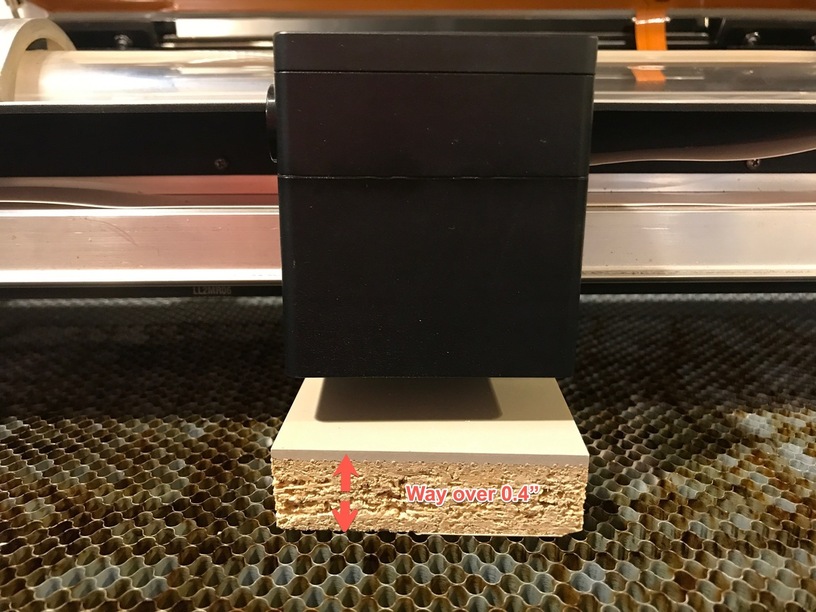
The GlowForge has a maximum material thickness it can cut through, but there is a maximum thickness you can even put on the honeycomb (crumb tray) even if you are surface engraving as the laser has a limited focus range of 0.01" - 0.4" *** above the surface of the honeycomb at the time of this tutorial. But let’s say you wanted to engrave something thicker that fits quite nicely inside the GlowForge but not with the crumb tray in place.

The process of figuring out how to cut with the honeycomb removed is pretty simple once you’ve gone through it. There are 5 steps (I will list them and then give detail):

  1. Measure how thick your material is
  2. Measure how deep your Crumb tray top is from the case (this is a 2-step process)
  3. Remove the tray from the GlowForge
  4. Find an object whose thickness is thick enough to put your object’s surface above the honeycomb and below the 0.4" limit
  5. Tell the software the material thickness is the height above the virtual honeycomb

Details:

Measure how thick your material is

This is pretty simple (for you non-Americans, sorry but you do need to use inches on your calipers currently - or do all the math in mm then convert at the end), just get the total average thickness. For a small item that is flat, likely one measurement is sufficient, but on a larger sheet, a few measurements of the area being cut onto is useful, and write down the average.


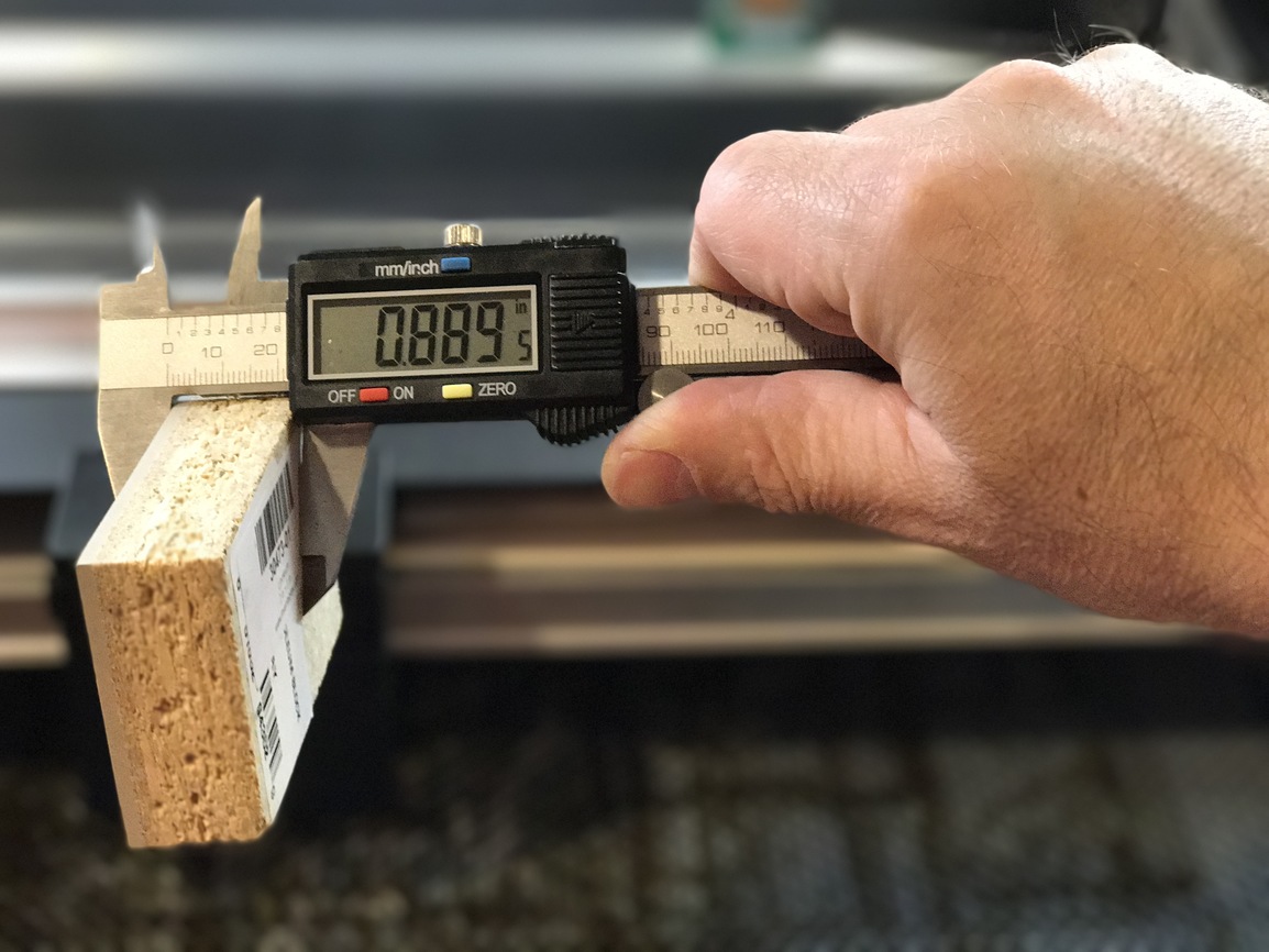
In this tutorial the Inventables Linoleum Stamp is 0.89" (in other words 0.49" thicker than allowed).

Measure the honeycomb surface height

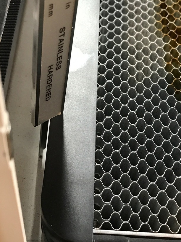
Now you might be tempted to just do this (don’t!):


(this is invalid as the honeycomb has an internal metal plate that is an actual crumb tray! You aren’t measuring the actual thickness!)


see the metal plate at the bottom sits above the case bottom.

So instead we need to perform 2 measurements, since your part will be sitting on the case floor, you need to measure the height of the honeycomb surface above the case floor:

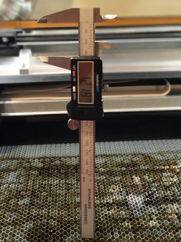
First measure floor to top of the tray using the depth gauge on your calipers (the spike that comes out the back)


(you can sort of sneak it into the corner)


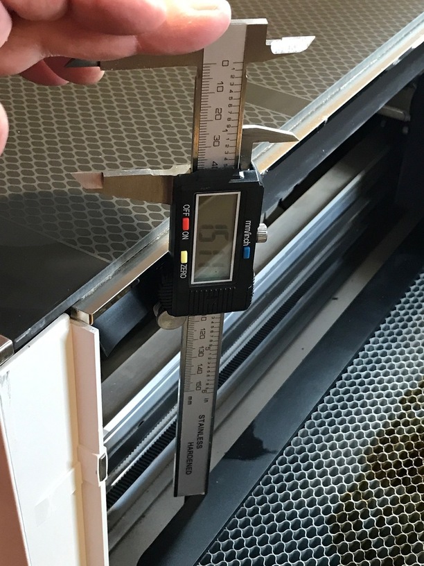
On this PRU GlowForge the height to the top of the tray is 1.511".

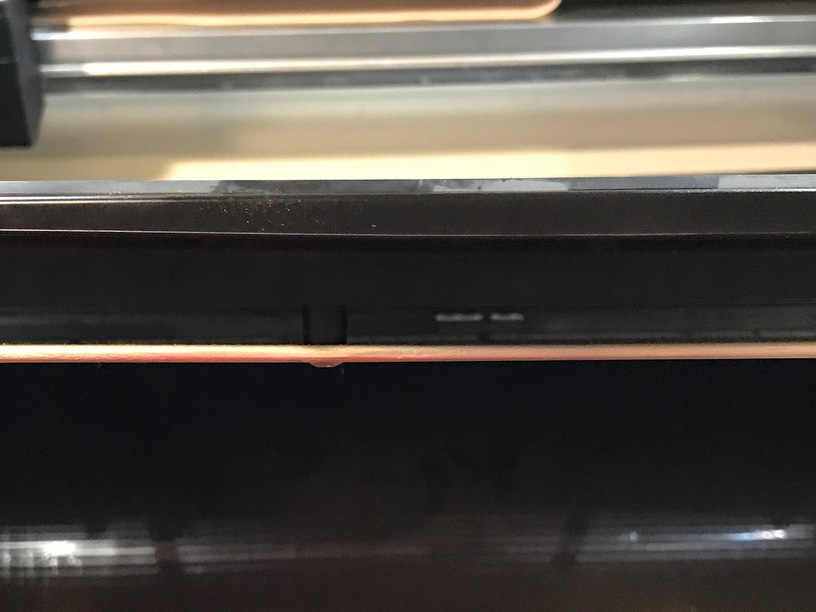
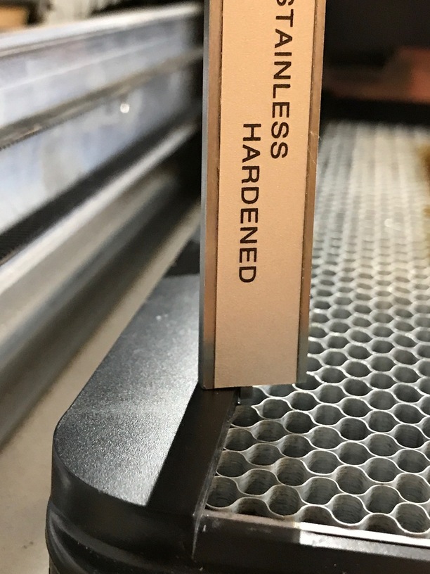
But wait, there’s more, because if you look you will note that the plastic edges form a nice square edge to place material against, but that is raised from the honeycomb.

So take your Depth Gauge and measure from the top of the plastic to the top of the honeycomb (yeah it’s thin, but you can make it work - remember you only will measure your tray once unless you change the tray out)

On this unit it yields a offset of 0.118"

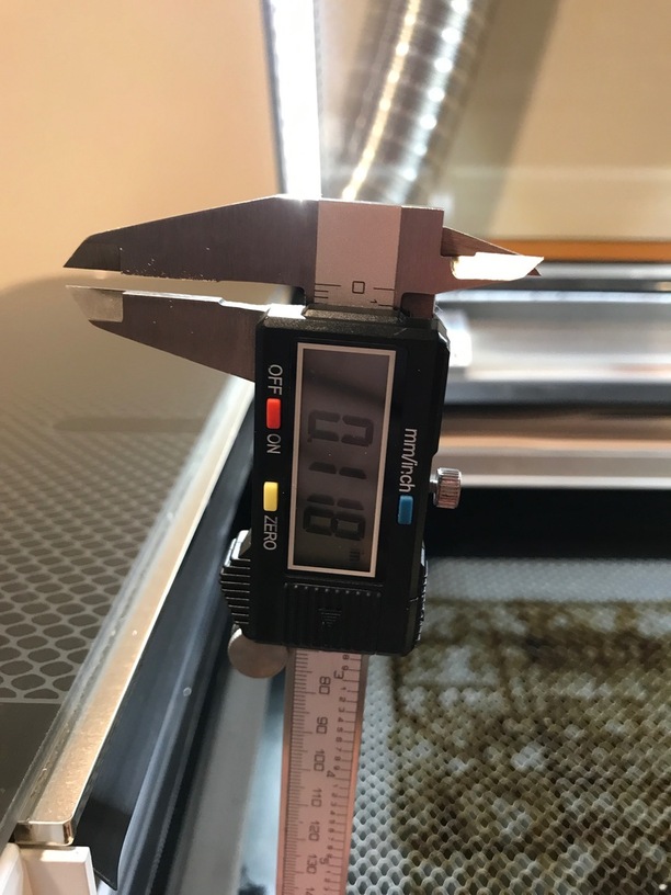
So our total depth of the case to honeycomb surface is 1.511" - 0.118" = 1.393" total thickness (let’s make that 1.4" in this case for simplicity)

Removing the tray:

The manual undoubtably will have a set of directions, but it’s pretty simple:

Handy tip, make sure the gantry with the laser on it is all the way at the back.
Open the front door, slide the crumb tray out with tipping too much so you don’t bang into the laser. Note it is heavier than you remember. Close the front door.

Find an object

Remember while the object you pick isn’t going to get lasered (hopefully) you might accidentally overshoot or punch a hole through, so make sure it is laser compatible (blocks of scrap wood work great) and that it is something that you don’t care about (scrap wood again).

So how do we know the thickness? Well we need an object that will raise our material surface into the correct zone of 0.01" to 0.4" above the height of the honeycomb. Now in our case since we have removed the honeycomb physically, we have a “virtual” honeycomb in our mind of 1.4" above the case floor.

So we need the following formulas

(Tray From Case Height + 0.4") - (thickness of material) = max height of object:

(1.4" + 0.4) - 0.89" = 0.91" (max height)

Now for minimum height you need to think about how deep you’re engraving/scoring/etc, because you need to make sure that operation is within the focal range. So let’s imagine we want it to be 1/8" above the bed (0.125")

Tray From Case Height - Thickness of material + desired new height = minimum height

1.4" - 0.89" + 0.125 = 0.635"

So I need an object somewhere around 0.64"

So luckily a brio train track and a piece of scrap proof grade maple ply were sitting around:


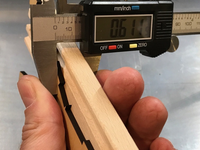
(yeah, not exactly what the example was calling for, but I just need to change the number I put into the GFUI to reflect that it is lower by 0.029")

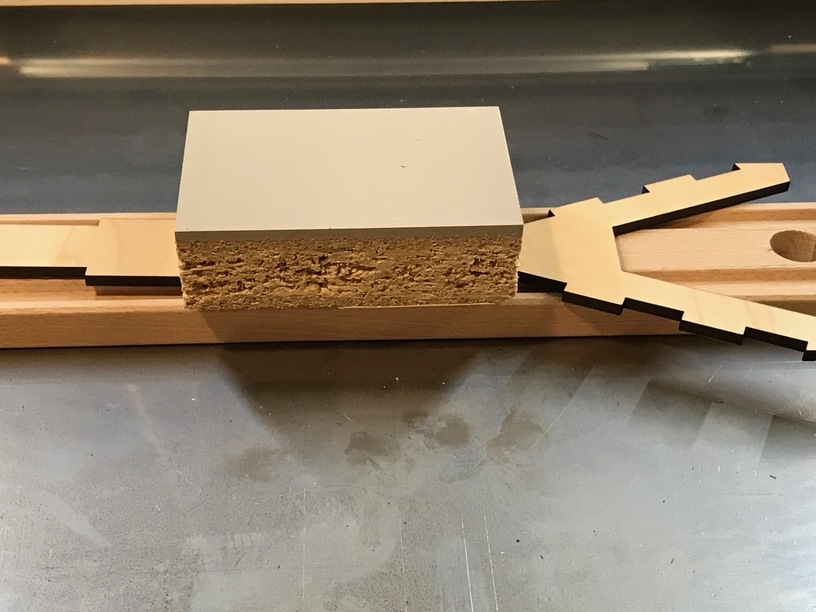
So stack it all up like so

And in the GFUI you are going to enter the material thickness according to our derived thickness:

(Height of our object + material thickness) - Case to Honeycomb height = GFUI entered thickness
0.61" + 0.89") - 1.4" = 0.1"
(note if it comes out negative you are too thin [below the virtual honeycomb] and if it is above 0.4" you are still too thick)


***.

I’m going to add this here to @henryhbk 's excellent wiki tutorial, since it came up in another thread, and it explains just what we’re shooting for:

You have to place the top of the item to be engraved within a range that falls from 0.01" to 0.45" from where the top of the crumb tray normally resides.

A quick diagram to explain it:

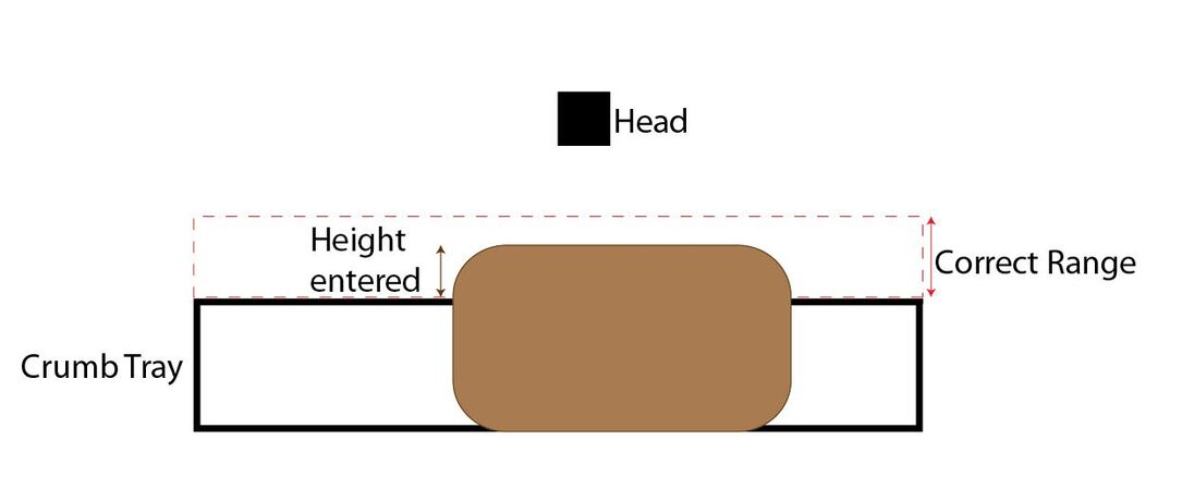
The top of the crumb tray is 0.0" as far as the interface is concerned.

175 Likes

Easily understood. Just a minor update. The user interface currently allows a focus range between 0.01 and 0.433".

7 Likes

interesting, when I started working on the tutorial a while ago, there was a message 0.1 - 0.4", I guess now we can go to 0.433 (but unlabeled now)

5 Likes

Nice, you got all technical and I’ve just eyeballed it and it has worked great for me.

10 Likes

Very good writeup. I’ve been using 1.361 as my crumb tray measurement. I only engraved on cutting boards and didn’t have to worry about the lid focus measurement for placement. Will have do do some more testing. The biggest issue is not having something too thick that the air foil scoop for the air assist doesn’t grab it.

1 Like

Oh thank you so much! I only did it once and I’m pretty sure I did it pretty much the same as you (it worked fine anyway), but it’s great to have a step-by-step to refer to for next time. Otherwise I’d have to do it from scratch again.

Thanks for the details write-up!

As a father and, well, a human being, I have a ton of LEGO blocks that I think I’ll use to build stands with the tray removed. It’ll allow some pretty decent scalability I’d think. I realize they’re not a laserable material, so maybe a top layer of cardboard will be in order. Guess I’ll try it and see how it all works.

9 Likes

I have a couple dozen 12"X12"X3mm BB ply on hand all the time for prototypes & POCs (after my initial attempts on chipboard) so it’s easy to slide a couple (or a few) sheets under my oversized pieces. Makes it easy to adjust the height pretty quickly.

Not unlike my K40 when I first got it (I’ve since put in a lab jack to use as a Z-axis adjustable table base) but it’s 100 times easier because if the big front door that makes crumb tray removal/replacement simple as cake.

3 Likes

Nice write up! Another option is to put something rigid across to top (with the door open!), measure down to the crumb tray, and subtract the thickness of your cross piece. Then repeat with the crumb tray out.

6 Likes

The crumb tray dimensions are pretty much the same between every 'forge and unlikely to change, so you can crib from @henryhbk’s homework. :slight_smile:

32 Likes

I threw out all my cheap calipers that looked like yours because they all had a bug where they would jump 0.2". Some did it from new and some developed it over time. I read that it is because they ripped off the Mitutoyo design but got something wrong. I bought a couple of genuine Mitutoyo ones at great expense and they work very well. Unfortunately they don’t do inches, so I really hope GF will support metric units. Otherwise I think it will be the only non-metric equipment in my home apart from a few expansion rulers and a micrometer I inherited from my father. Everything else is either dual or just metric.

Why do you need to enter a material thickness? I thought GF currently measured it with the head camera for auto focus. Can it not measure it with the crumb tray removed? It isn’t really thickness, it is actually the Z position of the top surface.

5 Likes

I’m gonna have to reread that , but thank you sir. I believe I just learned more ,and I am mathing again. YAY

You are correct it is the Z of the top surface, but you enter it into a field called material thickness, so that seemed easier to use.

I believe (since that is when you see the effect) it is for the lid camera to determine the size of the object for alignment.

5 Likes

Seems to make the auto focus pointless if you need to measure your sheet and enter it first. I don’t see why it can’t get a rough image of the object with the lid cam, accurate enough to send the head camera to measure its thickness and then correct the lid camera image for that thickness.

6 Likes

You enter material thickness only to correct the distortion for the lid camera. The image is significantly different if the distortion is adjusted with an incorrect assumption of material thickness. The actual material thickness measurement from the head is made after you have optically positioned the design over your material. Yes it could be done automatically if the unit knew where on the bed you wanted to take a measurement. It doesn’t, so it can’t.

4 Likes

Good idea, and seems trivial to indicate the desired spot in the GFUI. Paging @Dan - can we get that in the hopper?

It does give a crude image (parallax distorted of course without depth), you still need to do the above calculations to make sure you are in the focal range of course, but yes we could eliminate typing it in.

3 Likes

Yes although you could make a pair of depth gauges to judge the gap to the head is in range, which is the way cheaper lasers are focused.

3 Likes

Shars sells some nice middle of the road calipers that seem to be accurate, display metric and Imperial units, and some models have a large display for aging eyes. The main issue I have with them is that you have to press the on/off button to power them up and some brands will power up when you move the jaws.

http://www.shars.com/products/measuring/caliper

Same number of steps whether you enter thickness at the beginning or you enter position for the head to take the thickness. There is no way for the S/W to figure out where you want the design cut until you overlay the design. Easier for me to remember the material thickness for stuff that I have already used than it is to measure an X,Y every time. And you can’t place the design over the image until you have a good undistorted image, which means you would have to wait for the head to measure the thickness before placing the design, and if it measure in the wrong place on non-flat material or material that already has been cut then the material thickness is off.

3 Likes

Hopperized! (cc @Tony who has been thinking about this experience)

3 Likes