This is fully modeled, but I have yet to receive GF yet in the mail so the design is not currently implemented in the physical world. Constructive criticism is welcome and appreciated.
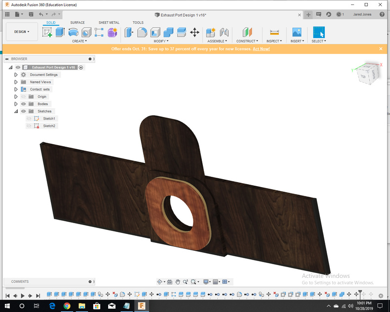
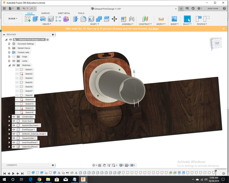
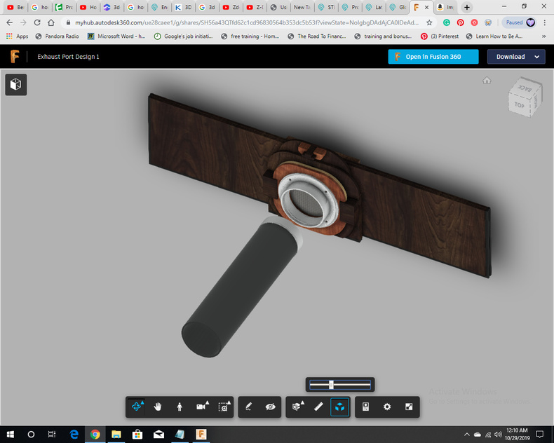
This is an exhaust port designed to vent fumes out a window from the GF through the included dryer ventilation hose. The finished product will sit inside the window sill and allow the fumes to easily pass into my backyard. All parts are designed to be laser cut or are easily purchased from Amazon.
I’ve taken suggestions written in comments for similar projects and incorporated them into this the best I could. For instance, I’ve included a sliding draft blocker to stop backdraft when the GF is not in use. I’ve used neodymium magnets to make coupling/ decoupling a simple process.
I’m considering adding an internal fan when I get around to the second version. When I add it, I’ll also make sure that the fan plugs into the wall and is smart/ arduino controlled.
I based this design of the exhaust port in:
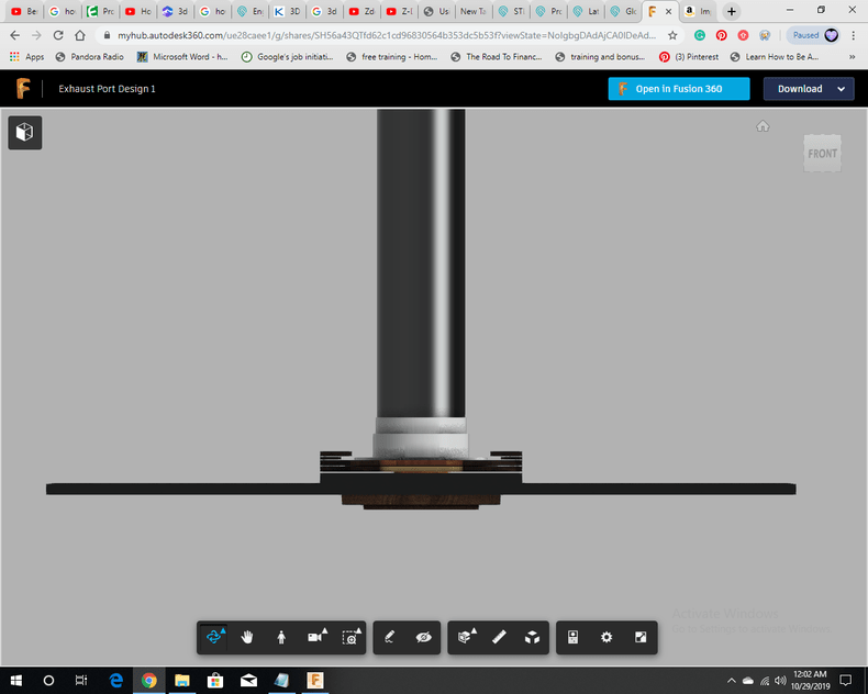
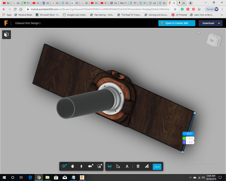
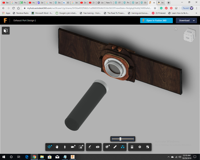
View a 3D version at:
(it can also be downloaded there to be used with fusion 360)
I know this is old news. Others have been making these ports and releasing their designs on this community forum for several years now. What I’ve done is only a slight variation on the old, nothing new. I’m new to the community though and thought I’d post my 2 cents anyway.
That being said, I’m very satisfied with the design.
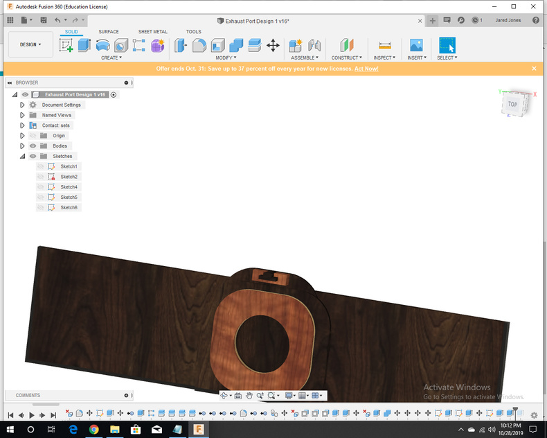
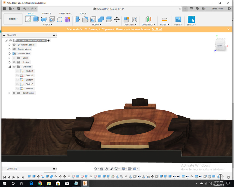
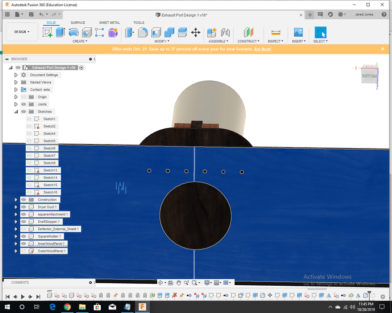
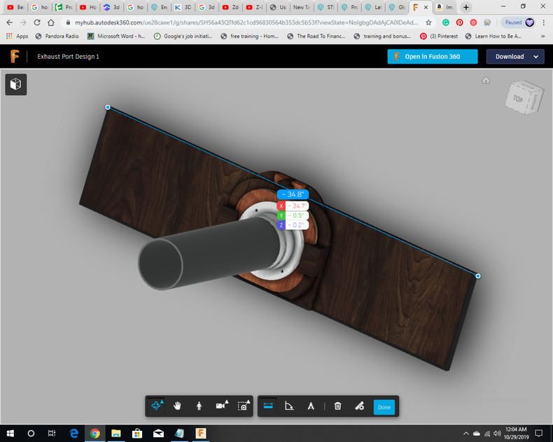
Step 1: Created the base sketch based on the size of the duct, the width of the window, and placement of the magnets,
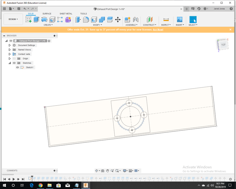
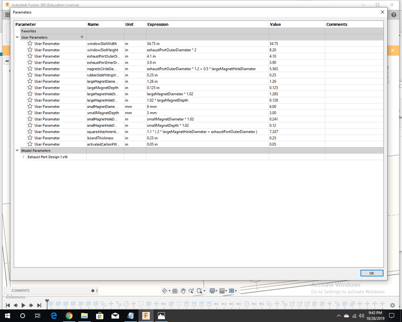
Just a simple sketch. I made sure to keep track of useful parameters as I went.
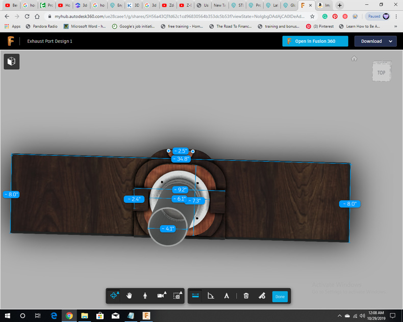
I measured the width of the window (from the inside of the track) to be 34.75". Outside the track, the width was 36".
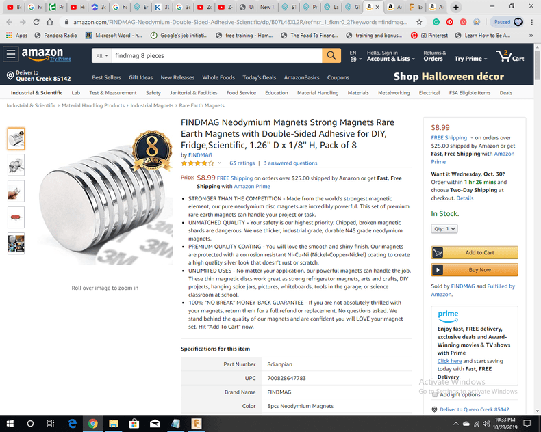
The neodymium magnets are from FindMag:
# 1.26’’ D x 1/8’’ H, Pack of 8
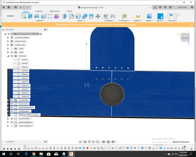
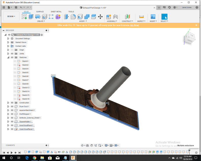
Step 2: Extruded basic parts
-2 window boards, inner and outer
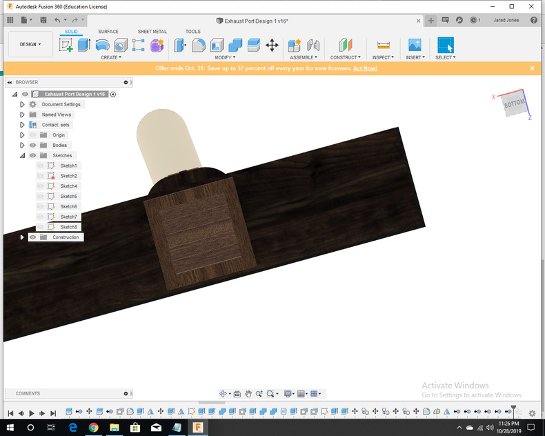
-2 square attachment pieces, which fit together. An activated carbon filter fits between them. These will later be screwed together.
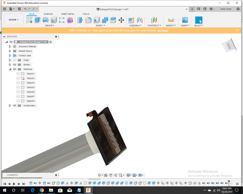
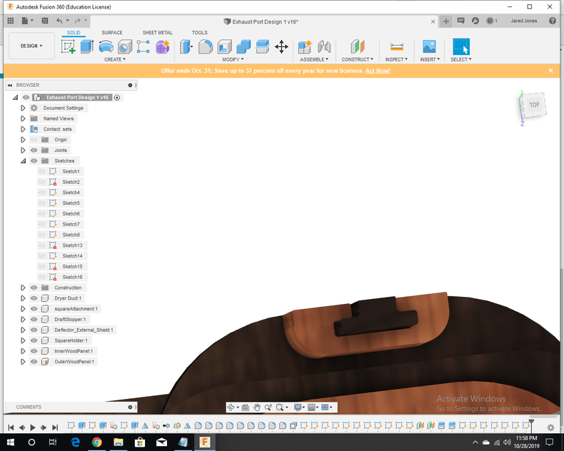
-1 draft blocker, a board that slides behind the square attachment to stop a slide down and block backdraft while the GF is not in use. It is fastened to the bottom by magnets. It also is suspended by magnets while the GF is in use. It needs to be held up so that air can flow beneath it.
I then added a handle on the draft blocker.
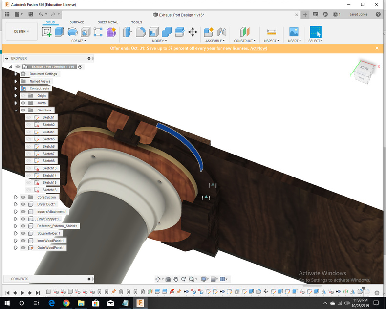
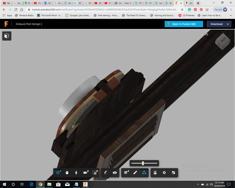
The square attachment slides into place and then is secured by wooden clips on the side and curved holders on the bottom. That way, the magnets don’t have to do all the work and even if the hose is jostled, the square attachment will at most shift and then snap back into place.
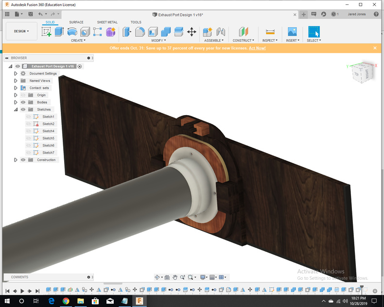
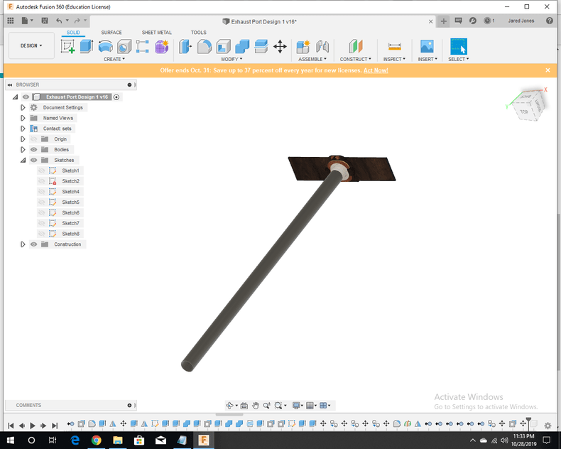
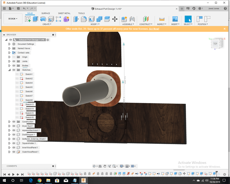
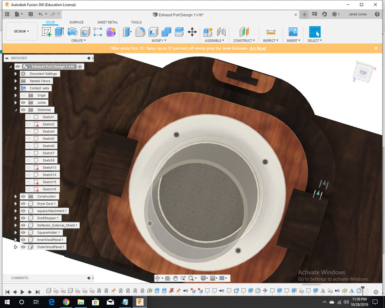
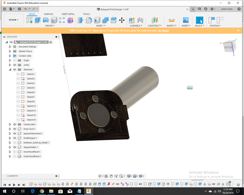
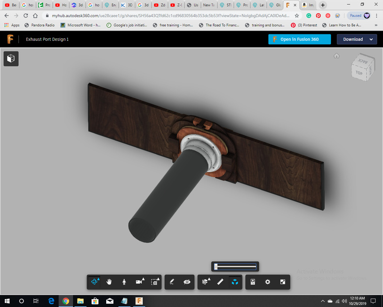
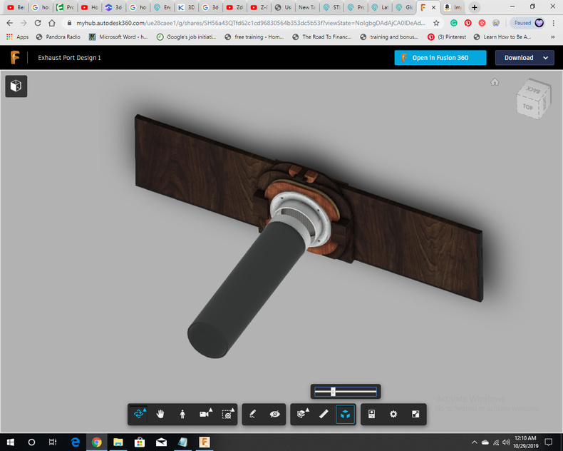
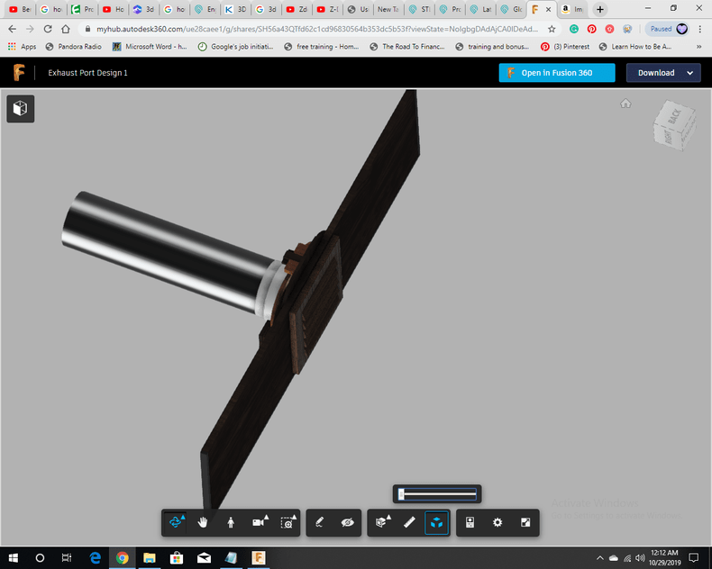
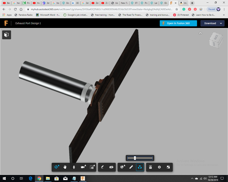
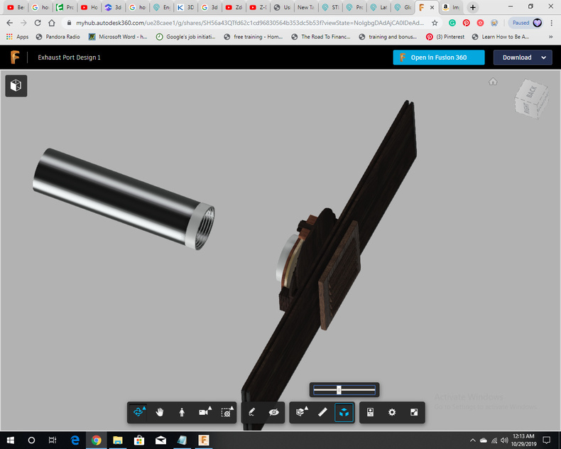
Step 3: Designed a model of the dryer hose, a model plastic 4" duct to wall connector, and a model 4" Louvered Vent Cap
The duct to wall connector can be found here
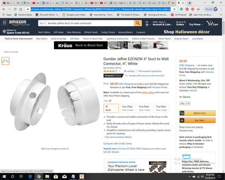
This was one of the easiest parts to design.
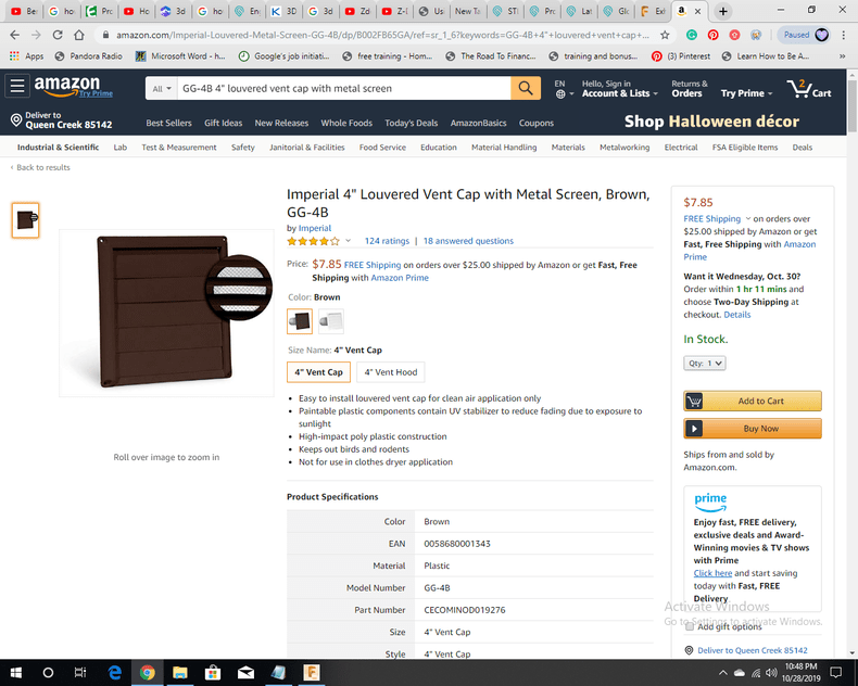
Next was the louvered vent cap. The version I found on amazon is brown like wood and has a metal screen inside.
The louvered vent cap can be found here:
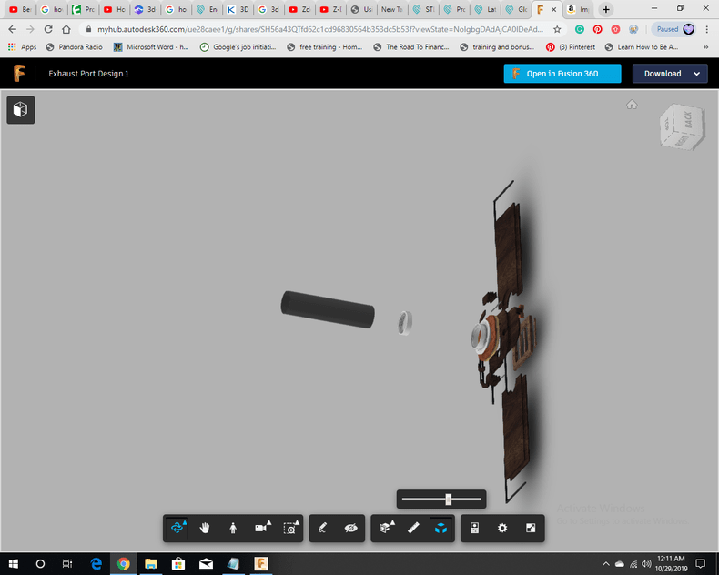
The full 8’ hose included for comparison:
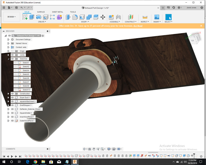
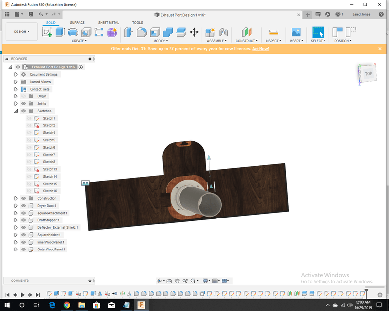
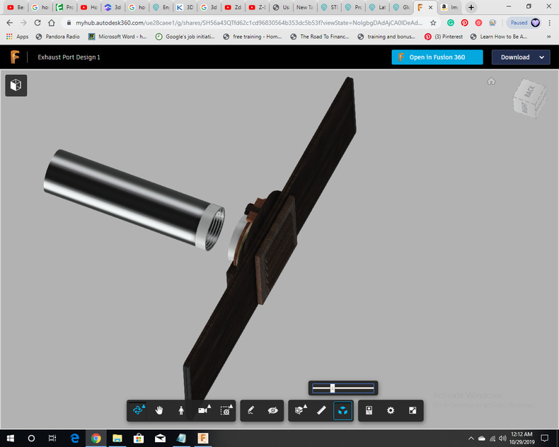
Step 4: I rotated the duct to wall connector to avoid the screw holes conflicting with the magnets
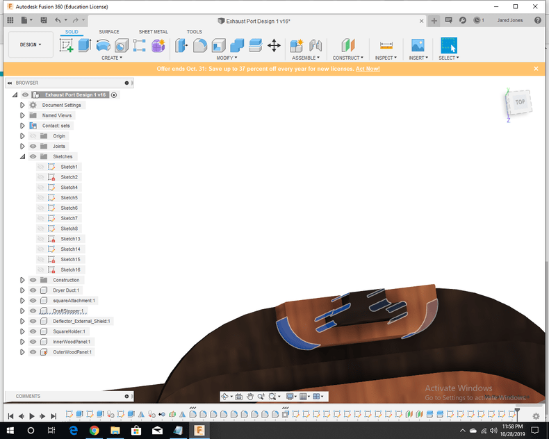
Step 5: I added activated carbon filters between the front and back square attachment blocks and along the edges of the slot for the draft blocker
Not much to say here. I just measured the thickness of the activated carbon filter I had to be close to 1/20" when not compressed, and assumed that a 20% compression should be sufficient (down to 2/50") to halt stray fumes from rising into my room.
Notes:
-
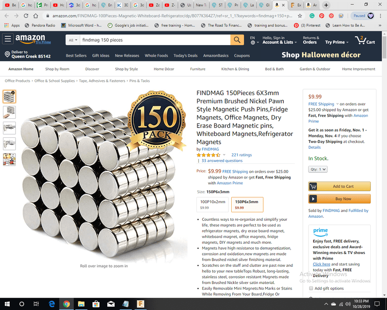
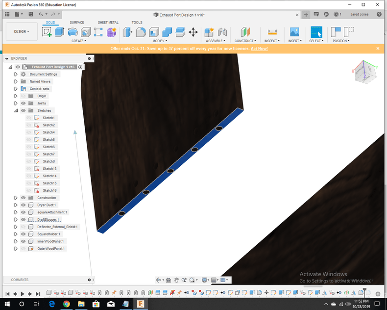
Some holes will need to be drilled (this is mostly for the 6mm x 3mm magnets)
-
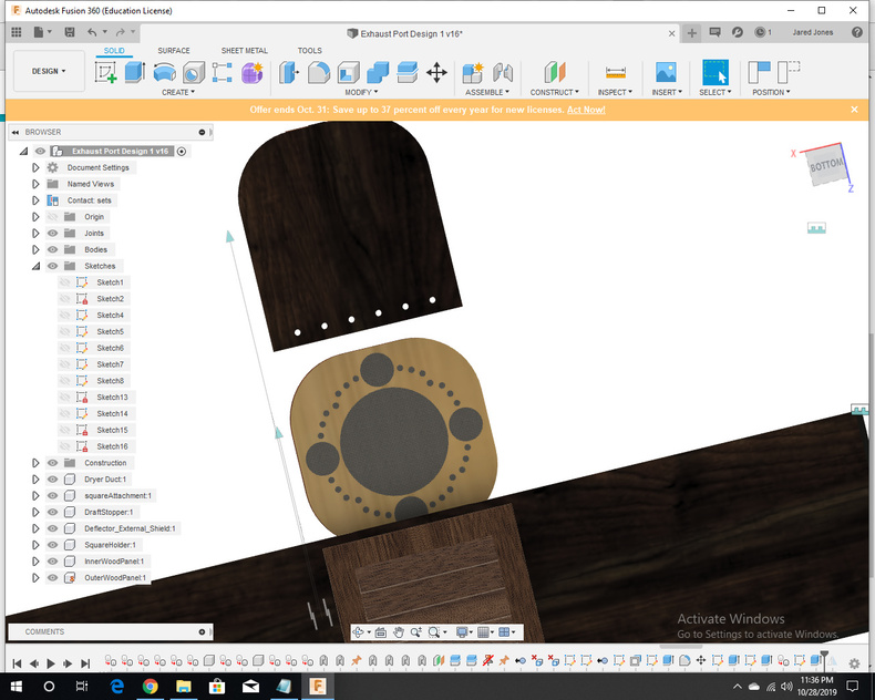
The magnets will be arranged N - S, N-S to ensure max holding strength
-
I may add a thin steel ring within the magnetic field of the circle of magnets if needed (Though I doubt it after feeling how strong the neodymium magnets from FindMag are)
-
The draft blocker has magnets on its bottom and on its side, near the top. This is to seal it when it is closed, or to suspend it while it is raised.
- The square attachment is meant to smoothly slide down and lock onto the other magnets. I imagine some force and initial momentum will be needed to carry it into place and avoid locking onto other magnets.
- Fillets were applied to the handle to make it smoother on the sides and to ensure a clean fit
-The hose and square attachment should be able to easily slide out without removing the draft blocker
- Extra space is made between each of the parts, but they should smoothly fit into each other once the parts are glued/ screwed.
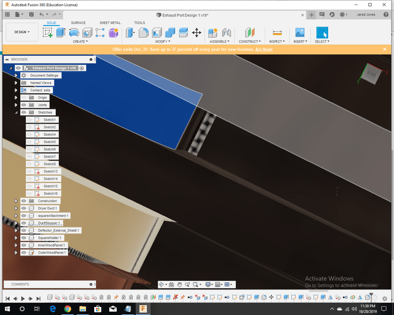
- It isn’t too important, but I added rubber edges that will be cut and glued on:
- Here are some dimensions at a glance:
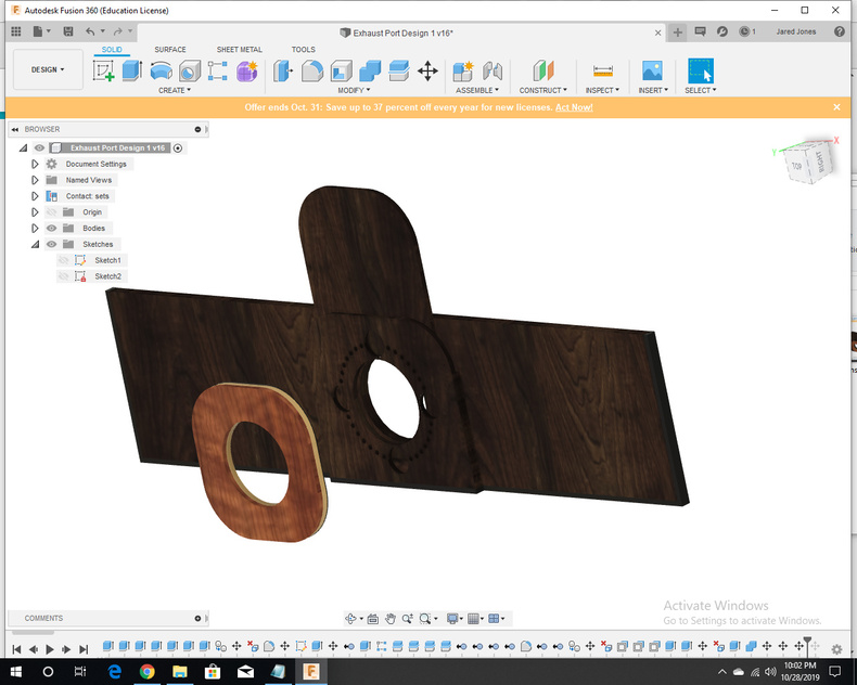
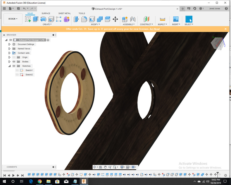
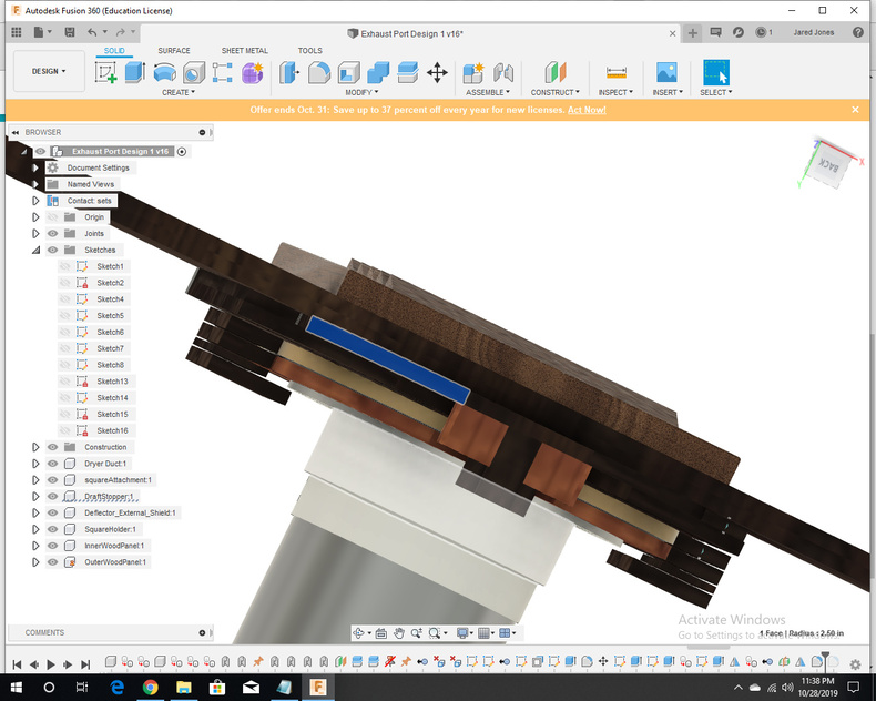
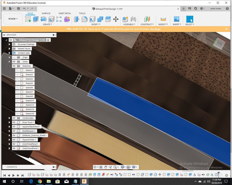
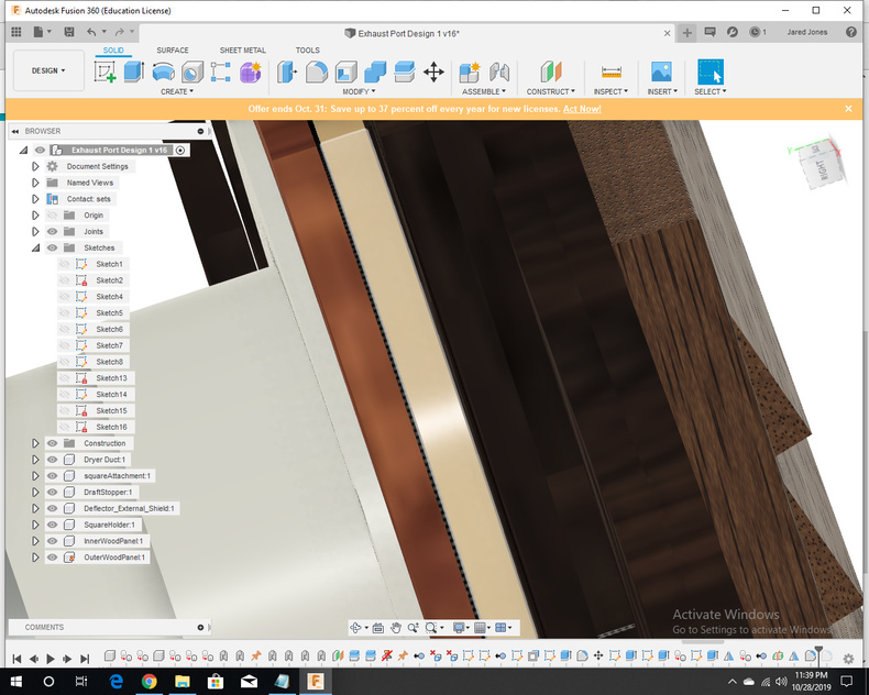
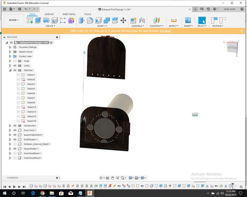
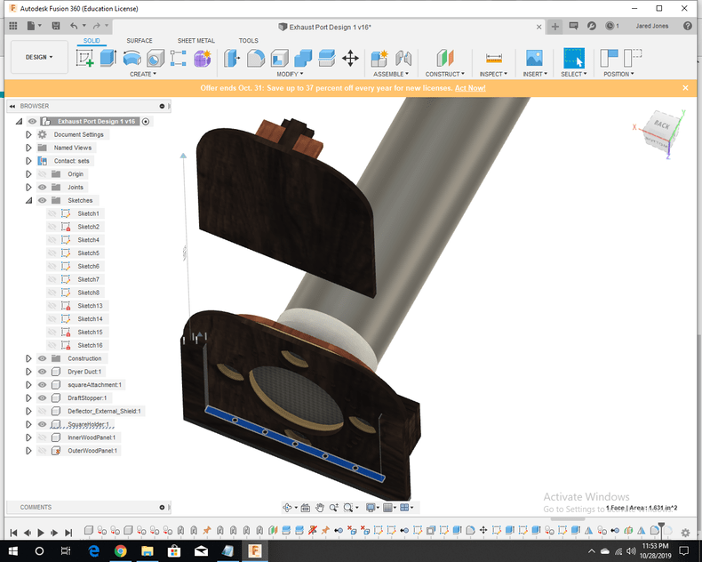
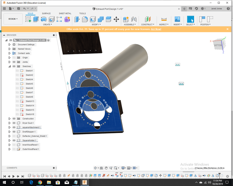
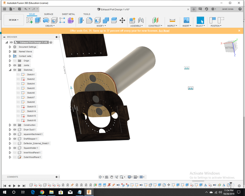
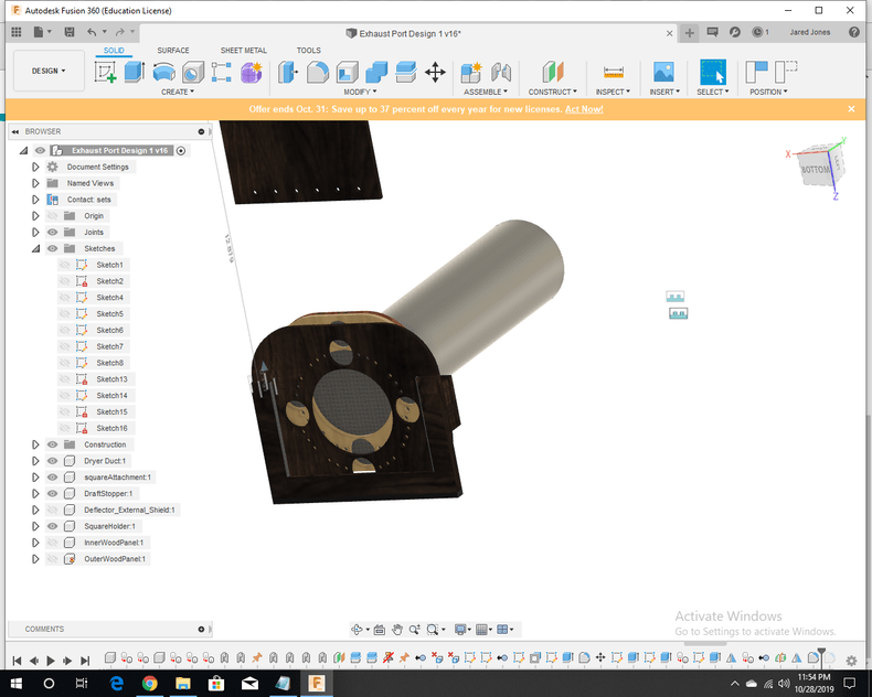
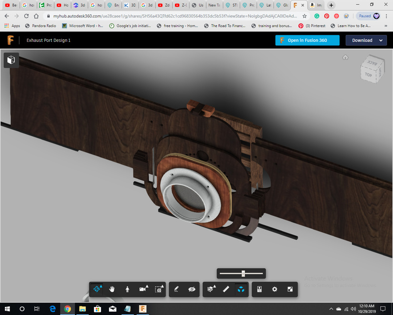
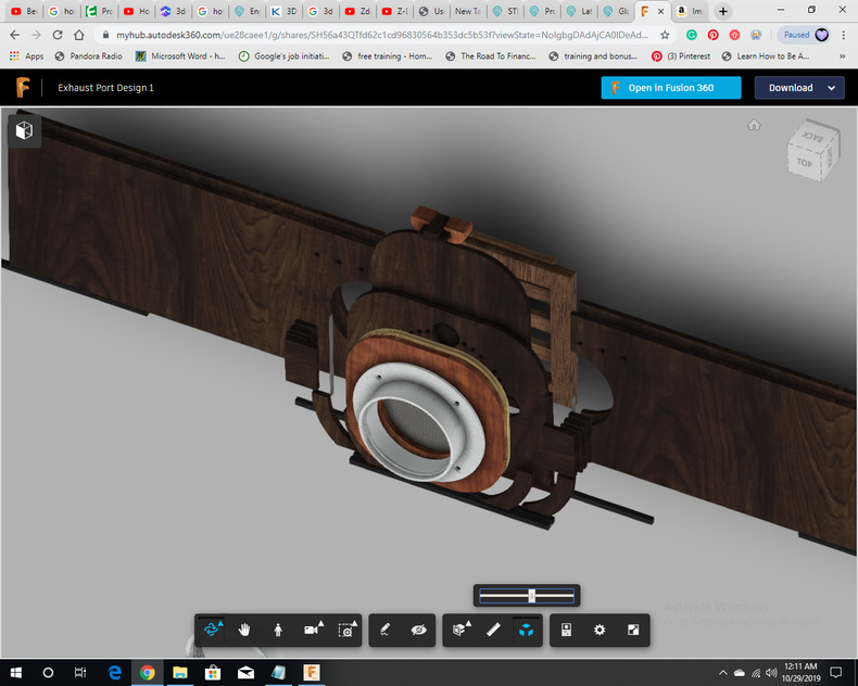
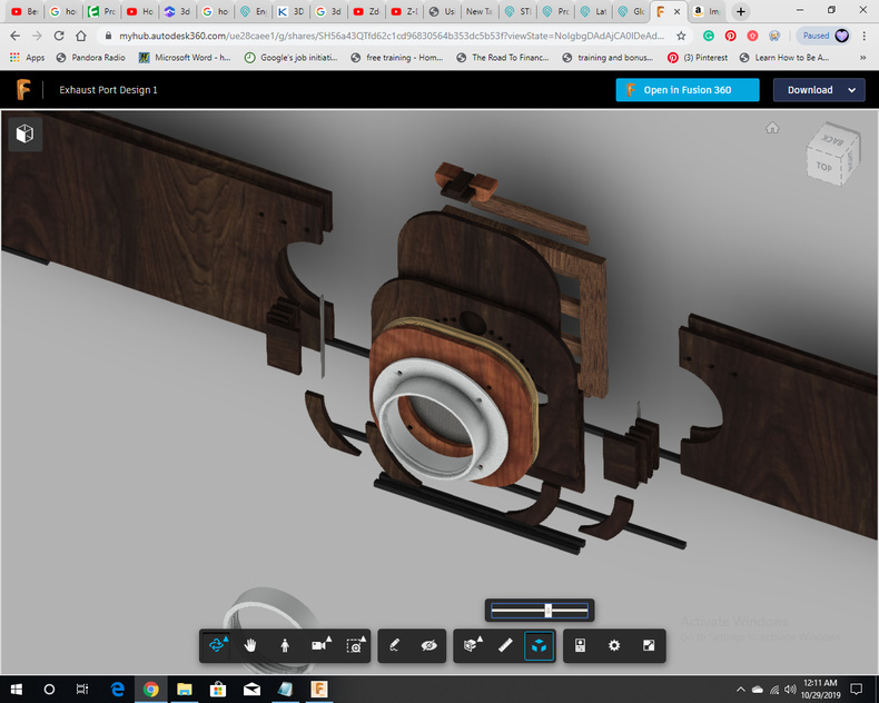
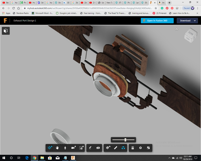
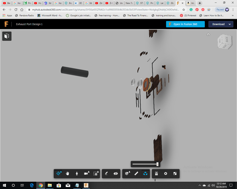
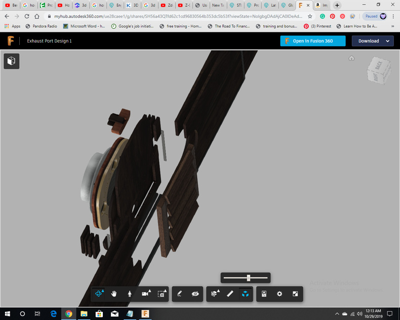
- Exploded model snapshots:
Conclusion and DXF FILES
As I mentioned before, all these parts (with the exception of the louvered vent cover, duct to wall connector, magnets, screws, and glue) are meant to be laser cut.
By default, all are cut from .25" material.
InnerAttachmentPiece.dxf (7.0 KB)
This is a permanent fixture that holds magnets for the square attachment to slide onto.
InnerWoodPanel1.dxf (2.8 KB)
Left side of the wood panel inside room
InnerWoodPanel2.dxf (2.8 KB)
Right side of the wood panel inside room
InnerWoodRubberOutline1.dxf (2.2 KB)
Left rubber outline. This is for both inner and outer wood panels.
InnerWoodRubberOutline2.dxf (2.2 KB)
Middle rubber outline. This is for both inner and outer wood panels.
InnerWoodRubberOutline3.dxf (2.2 KB)
Right rubber outline. This is for both inner and outer wood panels.
lowerSideHolder.dxf (2.2 KB)
These are the rectangles which make up the lower side holder. There are Three on each side for a total of Six. Two on each side are cut out of 1/4" material. One on each side is cut out of 1/8" material.
OuterWoodPanel1.dxf (2.3 KB)
Left side of Outer Wood Panel (from the perspective of someone standing in the room and looking at the wood panel fully installed)
OuterWoodPanel2.dxf (2.8 KB)
Right side of Outer Wood Panel (from the perspective of someone standing in the room and looking at the wood panel fully installed)
squareAttachBottom.dxf (7.2 KB)
This is the lower half of the square attachment. It holds the magnets.
squareAttachmentFilter.dxf (2.5 KB)
This is cut out of an activated carbon filter material and fits between the two square attachment pieces
squareAttachTop.dxf (2.6 KB)
This is the top half of the square attachment piece. The duct to wall connector is screwed into this piece.
squareHolderBaseRubber.dxf (2.2 KB)
The rubber at the base of the square holder.
topSideHolder.dxf (2.2 KB)
The naming may be confusing, but this is the top part of the wooden clip on each side of the square holder. This holds the square attachment in.
bottomHolder1.dxf (2.3 KB)
This is the left bottom holder for the square attachment piece. There are two bottom holders cut out on each side.
bottomHolder2.dxf (2.3 KB)
This is the right bottom holder for the square attachment piece. There are two bottom holders cut out on each side.
draftStopper.dxf (3.3 KB)
This is the draft stopper that slides down and blocks a backdraft.
draftStopperHandle1.dxf (2.9 KB)
This is the thinner, longer portion of the handle on the draft stopper. This should be cut 3 times out of .25" wood and then stacked.
draftStopperHandle2.dxf (3.5 KB)
This is the shorter, fatter portion of the handle on the draft stopper. This should be cut 2 times out of .25" wood and then stacked.
draftStopperRail.dxf (8.3 KB)
This provides the pathway for the draft stopper to slide up and down.
draftStopperRailFilter.dxf (2.2 KB)
This is the filter cut out that goes on each side of the draft stopper rail.
