XY home position

lid cam = inaccurate
head cam = supposedly way more accurate

they would have to leverage the head cam to allow us the accuracy we need in recognizing our jig location with the minimal margin of error

Hey All.

Whooosh, what a big thread.

I just did some registration-critical stuff yesterday with one of our older beta units. I’ll run thru what I did in case it’s useful or interesting. Note, all of the artwork in this post is me goofin’ in Photoshop.

A friend who is a founder of a smart-lighting startup here in Seattle wanted to do some user testing with some different iconography on the acrylic faceplates of their switches. He had a bunch of blank faceplates and asked if we could engrave them over lunch. I emailed a bit with his manufacturer to verify that it was acrylic, and here’s what we did.

Well, first, let’s look at an empty bed (artist’s representation!)

The non-whitened area is roughly what you’d see on the screen: some of the black plastic rails (raised on the sides, NOT in front/back), the head in the upper left, and lots of honeycomb.

The reddish area are mechanical limits of the head-- you can’t print here. Of course we want to make sure MATERIAL can go here so you can cut the maximum-sized rectangle out of a larger sheet of material (i.e. the raised side plastic is wider than the mechanical limits).

My friend wanted to make certain that his test faceplates were the exact same every time. While the camera is pretty darn accurate (and getting more accurate every day!), it’s a pain in the backside to drop a faceplate on the bed and fuss with moving/rotating/etc.

So, 5 minutes later, I had a (laser cut) jig and we were off to the races (well, we had to do a few tests engraves because it wasn’t our familiar Proofgrade acrylic).

Step 1, tape some scrap cardboard to the bed so it doesn’t move (shown: blue tape!).

Looks like this:

Step 2, Upload the faceplate design to Glowforge and drag it to the cardboard. You see something like this in the UI:

Step 3, Set the engrave part of the design to “Ignore” (i.e. it won’t print). Then cut out the outline and remove the rectangle. Now you have this:

That’s a jig. Now I set the outline CUT to “ignore” and un-ignore the engrave parts of the design. I open the lid, drop in the white faceplate into the hole I cut in the cardboard, hit print. When it’s done, put in new faceplate, hit print again. Etc. Looks like this:

As long as my source artwork has the shapes in the same place, I could load any number of variants of that faceplate design and have my jig work great.

You could also make an open jig (an “L” shape for more varied-size stuff).

In practice, we’re seeing the need for this level of precision is actually really rare… It pops up when you want to cut/engrave an existing object, but obviously doesn’t matter much when you throw a raw sheet of material in the bed to cut out a fresh design. It’s certainly common enough that we want to make sure that people can get precision when they need it.

(Warning: I’m out of my element here, so Dan might correct me if I’m mistaken!)
So, could I make a permanent jig of some kind that could be used over and over again? Depends on your need for precision, I think. We derive 0,0 based the camera and the head. And we calibrate this every time you turn on your Glowforge. Given that the head and lid camera are attached to things, and that those things can change, our sense of 0,0 could change very slightly. Example: there is a tiny bit of debris in the lip of our lid that causes it to be 0.1mm higher than it used to be. 0,0 just changed.

So, by example. Say you put a piece of blue tape in a spot on your bed and on the first of every month you opened the same svg file of a tiny square and hit print (without dragging artwork around at all). Would it always cut in the exact same place? In theory, yes. In practice, it could vary fractions of a millimeter because of computer vision stuff (that we can improve). It could also vary because your lid / head relationship changes somehow.

Fairly long-winded-- I hope it’s helpful for someone.

25 Likes

For doing these engraves all in one go, that will definitely work. The real trick is doing one, then having to do something else (meaning you have to remove the jig), then putting the jig back and doing another one and ending up with the same result.

Also… for me, a lot of things I want to engrave are existing items. Either crafted elsewhere by me, or being something that I own that I want to add detail to. In those cases, the cut a jig on the spot isnt so bad, but for the product kits that I create that are sold on a one-off basis, I need to have repeatability… and hopefully without cutting another duplicate jig that ive already cut

9 Likes

If there were some marker that we could put down on the bed, or object with markers on it to use as a homing point for the head AND physical guide, we know that we could get accurate, repeatable cuts every time.

btw @tony, thanks for taking the time to read this thread and converse with us regarding this

e.g.:

3 Likes

I know the horse is long dead, but:

What I get out of this is that if we can locate something consistently to the interior of the gf, we can use that as a reference that is accurate to the homing accuracy of the head. Which may or may not be good enough.

With MOST existing items, the notion is that you should be able to drop it in the bed, drag your artwork where you want it, and hit print with enough accuracy that you’ll be thrilled.

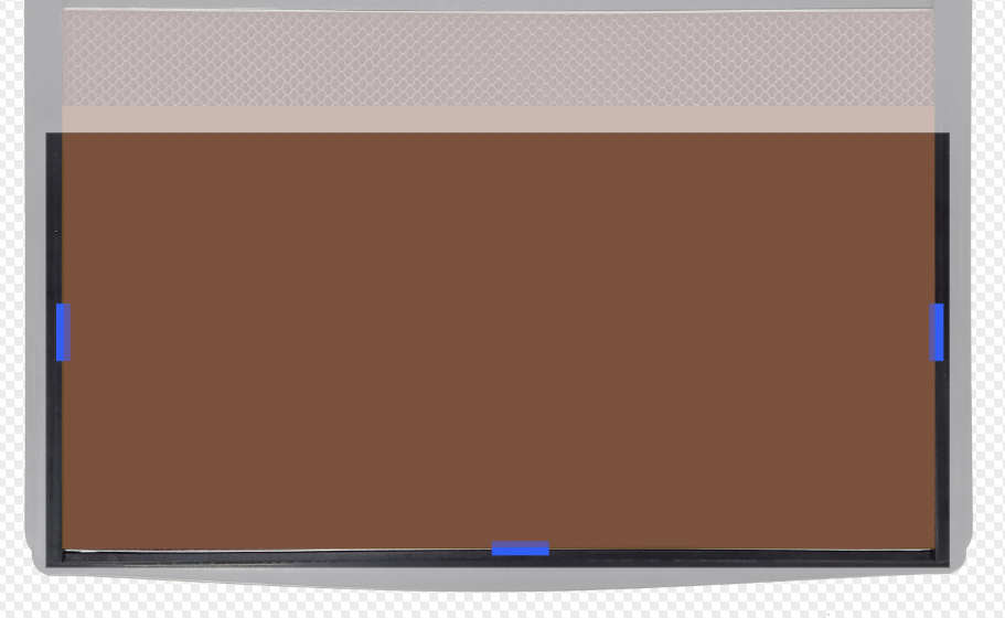
Another interesting way to look at it. Say you really want a sense of 0,0, so you taped a big piece of wood to your bed and cut out the largest rectangle you could. So you start with blue-taped wood like so:

And you cut out your largest rectangle like so:

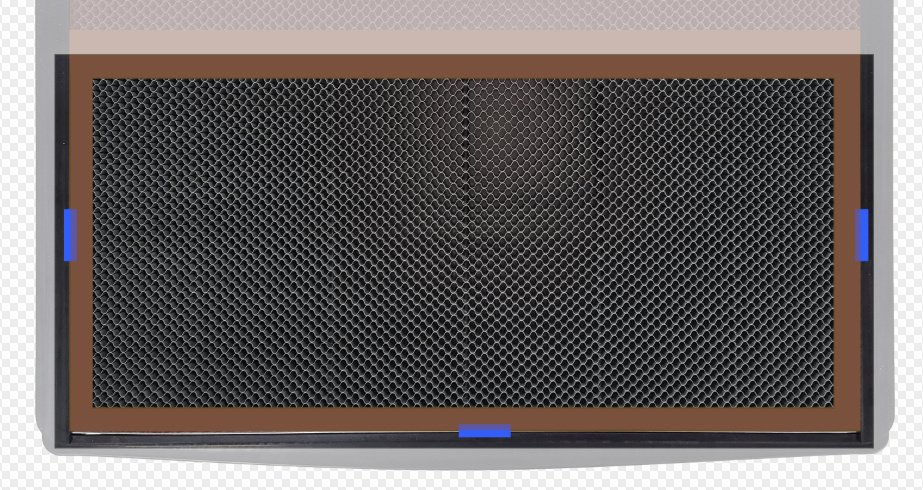
Is the top-left of that slot 0,0? Yes. You can use your original rectangle artwork as a template to key off of this corner. Is it possible that 0,0 could change VERY slightly (sub-millimeter)? Certainly yes on reboot (and we might add quick calibration checks, so it could happen other times down the road). Could it vary by more than that? Unlikely, but possible if the relationship between the lid camera and the head change substantively.

(standard disclaimer: I am a software designer founder by background, so Dan or someone else might correct/clarify what I’m saying!)

17 Likes

If it can locate the jig accurately then why can’t it just locate the work piece edges instead and dispense with the jig? Yes three fiducials are easier to home in on but Glowforge needs very accurate edge detection for the pass through to be useful. That is unless we have to add fiducials to our long pieces.

1 Like

Thanks @Tony!

Since @Tony and I have just said opposite things… :slight_smile:

I think Tony may be better at metaphor than I am… you can sort of think of it as 0,0 for purposes of print-to-print consistency; it does not appear that way in the UI.

That was what I measured for you above - registration of the camera is < 0.005 right now between a few reboots, and will get better when we add detection for the case of the lid being ajar.

The original example was a circle or arbitrary shape. The passthrough is designed to work with corners as reference points.

Note that the lid cam is accurate to ~0.001 when used to home the head, since the head is right underneath it (per my pictures above).

9 Likes

It just occurred to me that the two homing images (the two images of the :glowforge: logo) possibly aren’t as indicative of consistency in the head’s position as it may seem.

Since the head homes to the camera, images of the head after a homing operation really, really should be quite similar to each other.

If I homed to the camera and took an image (local01.jpg), turned the Glowforge off, physically moved the camera +5mm in X and + 5mm in Y, turned the machine back on and allowed it to home to the camera again, and then took a second image (local02.jpg), I would expect the two images (local01.jpg and local02.jpg) to be very similar to each other, even though the position of the head would be off by 5mm in both X and Y.

I feel like my hypothetical is confusing, so here’s something analogous…
Imagine two “speeding enforcement” cameras set up at two intersections of the same street. Let’s say this street is very uniform (level, no potholes, no turns, etc.). Let’s also assume the two cameras are set up in a very similar way (same height off the ground, same triggering mechanism, same angle, etc.). If an orange Corvette blows threw both intersections while going the same speed the photos taken by the two cameras would probably look pretty similar, even though the car was, in fact, in two completely different locations.

4 Likes

For the head to be in the same position under the camera, it must be in the same position in the bed, since the camera is immobile unless there are e.g. crumbs under the lip. In your analogy, they’d need to be the same camera at the same location.

1 Like

Isn’t the camera driving the homing operation?

If the camera is waiting for the logo to be in the exact right position before deciding that the machine is homed, there’s no surprise that the images taken by the camera after homing look similar. They’re only taken after it’s determined that the images will look similar.

Hah, I knew I’d get in trouble. 0,0 to me (designer) is “what is the most northwestern point on the bed where I can shoot laser beams”.

We are definitely thinking about ways to do reference points WITHOUT 1-off jigs. When we think about ways to solve problems, it’s always helpful to make it as “real-world” as possible so our design team can chew on it. Remember, we have to solve these problems in a way that works for you (pretty technical) folks, as well as the less technical folks that will follow in your footsteps.

e.g. saying “I’m going to sell customized light switch plates, which require precise engraving because the have to interact with the screw holes and the switch hole. I’ll be engraving 10+ of these per day. I’d love to be able to put 5 of them on the bed and have the engravings fit perfectly to the object every time”.

10 Likes

Mine is the north eastern point on the bed. :slightly_smiling_face:

@dan @Tony
ok I think ive got it. (I feel like newton crosby right now)

  1. take an SVG of an asterix (snowflake would be even better). cut it out of a piece of material maybe 6x6. acrylic or mdf preferably.
  2. remove the inner piece, you wont need it.
  3. place a thin piece of acrylic or mdf down underneath the previously cut asterix outline, and make sure the asterix is in a different orientation than it was originally.
  4. Now try to place the asterix svg as accurately as possible over the asterix shaped hole left in the original material and run a lower power cut thats JUST BARELY ENOUGH to make it through whatever material you put underneath.
  5. if you can cleanly and consistenly make it through that material underneath without touching the edges of the previously cut asterix, then you know you are capable of reliably producing an exact cut repeatedly. If you burn the edges of the original piece or dont have a consistent depth through the bottom material, it means theres probably still some work to be done.

kind of like a laser version of operation =).

1 Like

well at that point it might be able to, which would be great! I still think an L shape guide with 3 registration marks would be incredibly useful. especially if you have an odd shape material

1 Like

@Hirudin, I am probably out of my depth here, but what I’m understanding is that is the alignment test exactly. Because the camera doesn’t move once the head is in such a place that the camera sees it as aligned exactly right to the reference it is looking for, then in theory the head is in exactly the same place as it was before. The problem seems to be (and, yes, I know I’m restating what’s been said, but it’s how I learn :slight_smile: ) Because the camera is attached to a moving part–the lid–there is a chance of the camera being in a slightly different place if something is keeping the lid from completely closing or the lid warps, or something. Part of me wonders about using two moving parts as your points of reference for homing (lid and laser head), but I’m just the arm chair quarterback, glad they have guys much more clever than me working on this stuff :stuck_out_tongue:

If i’m following, then that’s where glowforge is coming from. I can see how developing a way to also take some kind of reference from the bed itself, using the camera on the head could, in theory, be a way to check the lid camera accuracy, or provide another default method for more accuracy.

Not trying to argue or anything. I’ve been reading this homing discussion for a while and am just trying to wrap my head around it. Right now I’m not foreseeing a situation where I will need the .001 accuracy, but I know I haven’t even begun to guess at all the ways I will use the machine so I might very well need it badly.

@Tony, like others have said, thanks for joining in a shedding some light.

3 Likes

Ok, thinking out loud (and replying to myself-which is normal because I talk to myself all the time). In theory adding a mark to the bed that he camera on the head lines up to exactly when the logo on the head lines up with the lid camera could, in theory provide an even more exact reference because now you are plotting through three points instead of just two. That would guarantee the lid, head and bed are all exactly the same relative to each other. Since the bed doesn’t move that would mean the head and lid camera have a “solid” reference to grab on to.

2 Likes

I think that’s a good idea. At the beginning I thought the head camera would be used more. Right now the head camera seems to perform focusing duty… and that’s all.

I started a new thread about the camera and dat dair head.

1 Like

lol, I was reading your reply when you edited it. I thought my eyes just glitch out for a second :stuck_out_tongue:

1 Like

Thanks @Tony and @dan for the very eloquent and timely responses.

To summarize where I’m at now:

  1. I understand the head home procedure using the lid cam on the glowforge symbol on the cut head. It would appear to give a consistent result for the physical position in the Glowforge based on lid camera. Lets call this the “cut head home” position. There is an offset from this head home position that dictates the bounds of the cut area physically inside of the unit, but it is not tied to the UI ruler. The upper left corner of this is what glowforge calls the (0,0) position. I completely understand that the head does not need to move to this position, but it does need to know where it is located inside of the Glowfoge so it knows it’s physical limits.
  2. I totally get the idea that you can cut a template hole outline (either the big rectangle from @tony or the @takitus snowflake), turn layers on and off without moving the template, and then engrave the part inside it.
  3. @dan Thanks for the clarifying response on the UI snap to (0,0) point on the ruler not being currently available {added to your hopper} and tying the (0,0) from the UI to a known offset from the glowforge cut head zero {added to the hopper}

My concerns have been heard by @Dan and has graciously added them to the list of development hopper items.


My pestering the subject relates to not having to perform several extra wasteful steps.

Current scenario:
Taping down cardboard blank for each new part to be cut (material and landfill waste), cutting out a hole (laser waste), flipping settings in the cut file from box outline to real cut or engrave to be performed (time waste), placing my real part to be cut in the machine, cutting the real part (real benefit). Any changes to the SVG file, (say I add something to make the lower left corner which make the SVG exterior dimensions larger) will change the file position when it is opened in the UI causing me to have to make a new cut a positioning template.

Alternate scenario if line 3 hopper idea is implemented:
Place corner guide to a known position (using side walls or whatever clever method you want) inside the Glowforge cutting area and simultaneously place the part in machine, open SVG file move it to the UI (0,0) where it automatically snaps into position, then cut the part. Yeh! No special steps! Part is cut 100% accurately! No waste! Changes to my SVG size don’t matter! I put it at (0,0) and cut will be in the right spot on my part. Yeh!

PS on the ruler idea for the Hopper:
4) I’m on board with @takitus idea of having a tool you could place inside the glowforge to establish the (0,0) position and angle in a location other than the upper left corner utilizing the cut head camera. I suggested the same thing back in response line 137.
Get me the two things in line point #3, and this is icing on the cake that could wait a long time.

1 Like