This would probably be best done with a set of jigs. At 30 degrees, your 2" of interior Z space yields (I think) 3.5" of width for the side. At 12 degrees, more like 9", which means you could cut a few edges at a time.
2 Likes
For me, it’s most important that there be hard stops that run parallel to the X/Y axes of the machine. A “raised square guide” as they’re called in the OP. If the stops aren’t parallel to the axes my world isn’t going to collapse or anything, but it’ll make cuttings things more difficult. Lasercutting and rectilinear designs go hand-in-hand and they’re going to be designed and set up on rectangular monitors and will be cut from rectangular stock. Having stops that are actually parallel to the lines in these rectangles will be helpful. We humans have a knack for identifying things that don’t line up, hopefully our Glowforges will help us avoid them.
The corner of the two stops doesn’t need to be at exactly 0,0 but the corner should be at a consistent coordinate. A consistent starting place is instrumental in getting consistent results. If the corner is at (-3.2,4.0mm), I’ll just add those numbers to any critical measurements that I’m working with. But if the corner of the bed is going to be those coordinates one day, then be (-2.4,3.1) the next day, and (-3.1,5.2) next week because they’re being placed somewhat arbitrarily by the homing routine, it’s going to have a negative impact on the consistency of things made on Glowforges and inconsistencies this large will be easy to spot with the naked eye.
I’m glad that the hard stop exist and I’m glad that it sounds like they’ll be reliably parallel with the axes of the machine and that it sounds like the corner will have a reliably consistent coordinate. 
2 Likes
How 'bout you create the shape of each type of mug bottom in your design and then set that shape to not cut. Center the words in that and use the non-cutting mug bottom shape for alignment using the camera.
There’s a ridge on the left and right that’s a “hard stop”, but not at the top, as that would make it impossible to pass things through or use oversized material. You could conceivably register large materials against the bottom. But you can easily fix that with your adhesive of choice and a piece of acrylic.
@takitus, if I was doing this, I’d create a cutfile with the box and the engraving properly centered on it. Then I’d tape down a piece of cardboard, cut the box shape, and put the object in the hole where the box was, then run the engraving.
11 Likes
so youre saying cutting a 0,0 corner for things like this isnt going to work? I need to make a jig every time? Theres no numerical offset positioning from 0,0 to manually create an easily repeatable cut?
3 Likes
I think I understand your use case. To me, the answer might be to add your circle to your existing file that did your initial cut. You’d center that circle in your app, line up your virtual cuts to your physical cuts via camera, then set the original cut layer(s) to Ignore, leaving only your new circle. Should be close to, if not, perfect.
But I don’t think I like it. I’d still like something physical. The same thing I used to line up the cut is what I’d want to use to line up any subsequent cuts/engraves.
I’ll admit, I might be over-thinking. I’ll make that decision when I get my 'forge.
The design to be engraved is already made in the program im designing in, I just dont have a bit that is fine enough to do it. I use a CNC router to cut the large stuff, laser to engrave the details on them afterwards. I dont mind throwing a bounding box around the design to make it larger or whatever, but I dont want to have to create a new jig every time I want to cut an object that ive made before. Cardboard is unfortunately pretty inaccurate as well, as pushing something against it can cause it to give, so Id have to use something more expensive.
Either way, I saw the accuracy of the optical system at maker faire, and it had a LOT of margin for error. I wouldnt trust an optical alignment (lid cam at least) on something like this when it can be done numerically. Im just confused as to why this machine has an accuracy of over 1000dpi but I wont be able to access it.
5 Likes
I definitely tend to agree with you. But, still, I’ll reserve my final judgement.
Won’t work to engrave the material first and then route? (Since you have an origin on your router?)
Sometimes this could work, but a lot of times it will not. Usually lasering is one of the last steps. CNC -> sanding/hand finishing -> laser engrave
2 Likes
Engraving on my wood knife sharpener handles the part that would be engraved is buried until after cutting.
3 Likes
This would be a good example of something that you would be doing a lot of that you wouldnt want to have to make a new jig every time…
2 Likes
Yeah, unfortunately, it sounds like for those specific applications, you’re going to need to come up with a work around of some kind…like a jig or a corner. 
Or maybe you can make your own rulers/stops/corners for the machine.
(I’ll also probably look into making something for it once I actually get it in my hot little hands! Chuckle!)
2 Likes
Thats what Ive been asking about and trying to figure out what will work. Sounds like youll have to cut a new jig EVERY TIME. theres gotta be a better way…
1 Like
Well, yeah, there is a better way - but they’re just not going to have time to implement it before these things ship. They’re built. (Metaphorically speaking here.)
They can look into something later as an upgrade to the software.
The ability to fit oversize stuff means that the no-hard-stop decision makes more sense to me. Because otherwise a stop at 0,0 would interfere with the bigger pieces.
2 Likes
Excellent point, and one I hadn’t thought of - but you’re right. That’s probably why they left it off.
I think that’s what Dan said here, no?
3 Likes
Lot of information in the recent updates! Totally missed it!
1 Like
Theres a difference between having a physical (0,0) point on the bed (which is cornered by a ruler or bar of some sort), and having a consistent software home position and software that will allow you to start a cut from a specific offset distance. My chinese laser had no physical (0,0) to align objects to, but it was super simple to cut one. I know this machine will always home to the same exact position, because it is using physical limit switches, so this physical corner guide is useful.
HOWEVER, if there is no real consistent (0,0) that the glowforge can determine, and it just picks a ‘close enough’ spot in the upper left area, there is no way to reliably create any sort of physical template to reuse for bulk projects. It may call it (0,0) this time, but next time you power on it could be (1.3mm, 0.7mm). If this is the case, everything must be done with a new jig every time. This is what Im most concerned about.
On a CNC machine there are workarounds for machines that dont have this, as you can use something like this to find the exact corner of whatever material you are working on:
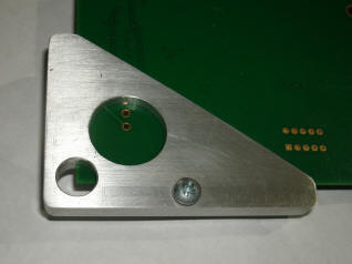
The tip of the bit and the plate are temporarily electrified, and when contact with the edge of the plate is made, the circuit is closed, it records the location of the edge, then records the other edges to determine that is in fact centered within the circle, right on top of the exact corner of the material.
However, as the glowforge doesnt work physically, you would have to have some sort of crazy optical sensor array that is impervious to laser damage to accomplish the same feat in order to determine where the actual corner of the material is down to any reasonable margin of error. On top of that youd have to have the software to support that type of operation which doesnt seem like something that will happen.
It does have the flying macro cam on the head itself, but I havent seen any mention of using this for homing. It would still be a bit of work to get that functional as well, and you would probably need a similar corner piece with a QR code for reference point.
Either way, at maker faire, the difference in location between where the images were placed on the material, and where they actually ended up when cut was pretty drastic. It was also a LOT more accurate in the center of the machine than towards the edges due to the barrel distortion of the wide angle lens. We had to put all of our cuts in the center for the demos.
Not being able to specify a starting point by numeric input will decrease accuracy even more and ultimately end with everything being eyeballed all the time. Im hoping this will not be the case, but there hasnt been anything to say otherwise.
4 Likes