Thanks @scatterbrains, that image helps a lot.
There seems be a flat bar on the bed close to the work-area limit (I assume it is permanently fixed). So now I know where to ‘shove’ and ‘drop’ my guide.
Can’t wait to start ‘shoving’ and ‘dropping’…
Thanks @scatterbrains, that image helps a lot.
There seems be a flat bar on the bed close to the work-area limit (I assume it is permanently fixed). So now I know where to ‘shove’ and ‘drop’ my guide.
Can’t wait to start ‘shoving’ and ‘dropping’…
Thanks for responding @Dan. What was missing all the time (or I missed it) is what to position the corner piece / jig against…
The image that Scatterbrains posted helps a lot.
Everyone has different approaches to understandiing. Over the past year I purposely didn’t bother asking questions about user interfaces, jigs, S/W design approaches, etc. Why? Because once the GF is in my hands I will realize that much of my planning has been for naught. Simpler solutions will suddenly become obvious or I will have assumed too much and have to completely rethink. Measure twice cut once.
I think @rpegg has the best conception here of what to do:
Chill out, don’t pre-think.
To be honest, the use cases where a hard stop at 0,0 that you can wedge material up against and you need to have done so are minimal.
The only thing which can align perfectly at a 0,0 corner is a rectangle. Most people who put a rectangle IN are not wanting to pull a rectangle OUT. ie - you are going to cut a shape out of the middle of this thing, and ditch the corners/edges as scrap.
In all of those cases… loss of a 0,0 endstop is a trivial loss.
In all of the cases where you are working with an initial “Not a rectangle” the loss of that corner is possibly a net gain, but at least not a loss.
So… the ONE use case where you want to have a 0,0 end stop, and may suffer for lack of it, is when you have something with a perfect 90 degree corner, and you absolutely do not want to cut away any of it (or you want to cut an insanely precise portion of it).
That simply is not a use case that will come up all that often for most people. Granted, for SOME people that is a “nearly every single time” use case.
But, it is still quite possible to create your own hard 0,0 stop. And there is a bit of a lip on the honeycomb which you could use (and keep a post-it with measurements for the offset from comb-lip to actual 0,0).
The manual drag and drop of your cut onto a picture of the bed will open up a lot of possibilities. But you will only make full use of this extra power if you actually use it.
Don’t judge the intelligence of the fish by asking it to climb a tree.
I’d like to put forth another use case where 0,0 might be particularly useful. (please remember, zero laser experience here)
What about the case where you have a piece that has at least one 90 degree corner and you want to precisely place an engraving on it that is a uniform distance from all of the edges? Lining that up by “eyeballing” it would be VERY difficult to be sure.
While the GF has workarounds for this kind of use case (scan the item in the middle of the bed, replace the item with a thin cardboard or wood to create a jig, test cut the image, put the item back in when satisfied about placement, let it engrave), I think it is a valid one to consider.
I think that having a 0,0 (or an M,N, don’t care about the number) is important for anyone who wants to do things more than once. Once I’ve made the jig for some job, I’d like a way to just plunk it down in the same place again, rather than doing the optical alignment each time. (And I think that cutting a corner piece and maybe some edge pieces should do fine for that.)
It is absolutely useful. And even though there has been much mention of “Make a jig” and counter of “I don’t like doing that” there hasn’t been much talk about what a jig is.
My latest repeat cut case on my own laser needed a lot of putting the material in precisely the right spot, because I was using the full width/height of the piece. I haven’t made myself a 0,0 stop yet (I swear, it is on the to-do list!) and wouldn’t have used it anyway (my laser doesn’t fire up immediately and so won’t cut the first 5mm or so of travel).
So, I “Made a jig”
This consisted slapping down a few sheets of paper, and running my job REALLY fast so it engraved onto the paper. I then put my work piece carefully over the engrave, laid more paper on top of that, and re-ran the fast run.
I now knew that my first piece was precisely where I wanted it, so I grabbed a bunch of thin magnets and put them all around the edges of my work piece. And lo-and-behold… I had a jig perfectly designed for my material and cut plan.
The cameras would have removed the need for me to do the paper engraving initial step. I could have slapped my material wherever, lined it with magnets so I can align the next one to the exact same spot, and then positioned the cut on screen (probably would still do the paper on top with fast engrave just to be REALLY sure I had the corners right though).
I was putting together a little jig creation tutorial last night when @dan answered the question…so I went to bed. Chuckle!
I can write something up once we actually have the machine and post it for folks who aren’t as familiar with it - it’s pretty easy to create some corners for the machine if you want to use them, or just make the jig part of your initial design the first time you run one.
And after that, it’s drop in your material and press a button.
(Would like to actually test it before i write it up though…just in case i guess wrong.)
And that will work if you have a bunch of repeat cuts to do NOW. But what about doing the same task next week or a month from now? How can I be sure that my next batch will be just as accurate as this initial batch is? I feel like I would need a 3 point assurance to know that my item and cut are perfectly aligned (with the 0,0 corner stop I’m assuming there are two “legs” in the x and y directions to give me the 2nd and 3rd point assurance).
I’m sure you’ve come across the situation where you have bought a card game of some sort, and you notice that the printing isn’t perfectly even across every single playing card. That is what I fear will happen with repeat cuts. Things may drift between cuts.
I don’t know that the 0,0 corner thing is the final answer. As far as I’m concerned if I had a Glowforge certified L block thing that I could toss onto the bed and the camera would automatically recognize it and it’s orientation and align the engraving based on that, that would be absolutely doable and acceptable. That way no specific coordinates are needed, as long as your item is a consistent size, and the software is capable, the engraving will be perfectly aligned every time despite the time and number of projects that happen in between each similar piece.
Depending on the material that you use for the jig, the sides of the machine can create your second and third points (ie: use wood to cut the jig, then align it in the same upper left corner each time and make sure that the sides are flush before you drop your material or items into the holes.). It should be right on the money.
I remember bringing up 3 Point Registration a while back, (can’t find it now though), but @dan and @Tony should be aware of it…They weren’t set up to code for it back then, and they had to continue as they had originally designed these things in order to get the machines done.
It’s a complete re-write of the code to do 3-Point Registration. The logic for how the head moves would use different reference points from what they are probably using now. (Can’t know for sure of course…haven’t seen it yet. But I trust that they have something in place that will work for what we want to do with it. We can create our own, physical, 3-Point Registration system using a jig.)
They might, or might not, opt to look into re-coding for it down the road, but they can look into whether it’s feasible or not after the machines ship, since it’s mainly a software thing.
In other words, it’s in
Good point. I rarely return to prior work, so just saving my file in the first place is hit or miss. I could see this being a nuisance for people who frequently return to prior work for one-off repeats.
For what I do, one of my top projects is to make Mugs. I’ll do an average of about 1-2 per month. With the Glowforge I want to engrave snarky saying on the bottom of the Mug that you will read each time you finish your beverage of choice. For this application, I would need to be reasonably sure that the lettering is equidistant from the walls of the mug. A repeatable jig would be more accurate than eyeballing the location.
I certainly intend to glue up the walls of the Mug first, and then draw my inner wall circle on the bottom to help with the alignment, but if I had a jig that would help me be even more precise, I’d like to do that.
And each mug will be a different shape, because they are hand made?.. I see.
Are you planning to cut the bottom of the mugs in the laser? Because if so, you would just cut and engrave all at once - you don’t need a jig, just the file.
I bet this is going to get more “wordy” than I initially planned.
I’m hoping to figure out how I can do almost EVERYTHING for the Mugs in my Laser. All I would have to do is prep 1/4 boards of wood in my shop and nearly everything else could be done on the laser.
With the exception of Variable Depth Engraving to specific degrees, everything else is looking very easy to do. And honestly, with my Table Saw, it might be easier to do the angles there anyway.
No problem then - I can help you work up a file to do that without ever having to set an origin anywhere. Very, very simple, and your text will be 100% accurate and centered before it’s even cut.
 That would be AWESOME!
Love learning new things about the lasers 
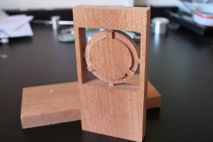
A common use case for me is that I CNC something out of a rectangular piece of material and leave it attached with tabs to then cut details on the laser so that I know they are exactly where they need to be.
Example:
If I wanted to engrave a circle on the dead center of this I can tell the laser exactly how many mms it is away from a corner piece set to 0,0. If I decided to do another one a month from now on my current setup I can do it no problem.
That is why I’m so curious if I create a corner jig, if I can get repeatable results via numeric offset, as opposed to eyeballing it on the glowforge.
For prop kits that are made to order this is incredibly useful and something that is done quite often for me. Knowing that I can type in a distance and it will always cut/engrave in the same exact space is pretty important for me. Hopefully the glowforge will be able to do that without issue, but it seems I will have to wait until I get mine to see what it is capable of.
Wrote this up, got distracted by work, and conversation has moved ahead of me… posting anyway before I catch up 
Non square, custom every time, and alignment absolutely crucial. Ouch.
If you will be using the laser to cut the bottom in the first place, then you could do up a jig which they sit inside of to get a nice rectangle for lining up with the top corner. I assume you already planned on that one.
Looking at the chance of making use of the camera as a bonus though…
If the walls of your mug are consistent (also done on laser, or other precision method so each cup interior is the same), you could cut some acrylic which sits on top of your jig + base. The top layer acrylic would be cut to have an opening which matches your inner wall. This saves you the drawing the wall step, and lets you align the text in the visual interface.
That one will absolutely benefit from a hard stop and repeat file positioning. The little bit of a lip on the honeycomb should be enough for your hard stop. Then it is a matter of getting the file set up so that however the UI happens to load files it will place the thing where you want it.
So… that particular case should be possible, but will almost certainly require more initial nuisance to set up than is absolutely desirable. It will mostly depend on how the UI is set up.
It would be really nice if we can save a layout so that after hand positioning everything we can just load the file and have all cuts be exactly where we had saved them. Barring that, if it automatically loads all models in the upper left corner (someone suggested that this appears to be the case based on videos posted of the UI so far), then it is still possible to pull off, but may require adding an extra part that you don’t actually cut (just to serve as the offset)
What Im wanting to know is if I can just type in a distance from 0,0 and that 0,0 is always the same. If thats the case I can just pull numbers from whatever software I create it in and not have to worry about fiddling around with it, saving files, creating unnecessary jigs etc.
It SHOULDNT require more initial nuisance. It should be incredibly simple. Its such a basic function of any CNC machine to say ‘set the beginning top left coordinates to X,X’. I mean they are doing that with the drag and drop, just not necessarily displaying those coords to the user. Hopefully this will be editable in the UI.