Hey everyone! I’m new to the forums. My name is Alan and I am primarily a 3D artist currently getting my Master’s in Fine Arts. This semester, my university was able to get a Glowforge, and I ended up taking a fabrication class where my professor really wanted us to push the Glowforge to its limits. Being a 3D artist, I immediately started looking into ways I could create large-scale 3D projects with Glowforge, and now I wanted to share my journey here and show how I created a full Dice Set and a 3D Torus all with the Glowforge! I know this is very lengthy, but it was quite a process and wanted to share everything I learned.
As I was doing my research, I found that, just like with 3D printing, one of the main goals of artists who use the Glowforge is often to make their product not look or feel like it came from a laser/3D printer. For example, most 3D Printers have a very layered effect that is aesthetically not appealing. We typically try to hide that effect as much as possible once it is finished by filling and sanding. Well most 3D Glowforge pieces use slice forms. This gives the same low aesthetic quality, but the biggest issue is that it is very difficult to hide the slice form after it is created. It is basically what you are stuck with aesthetically, and I believe it keeps many people from wanting to use Glowforge for projects like this.
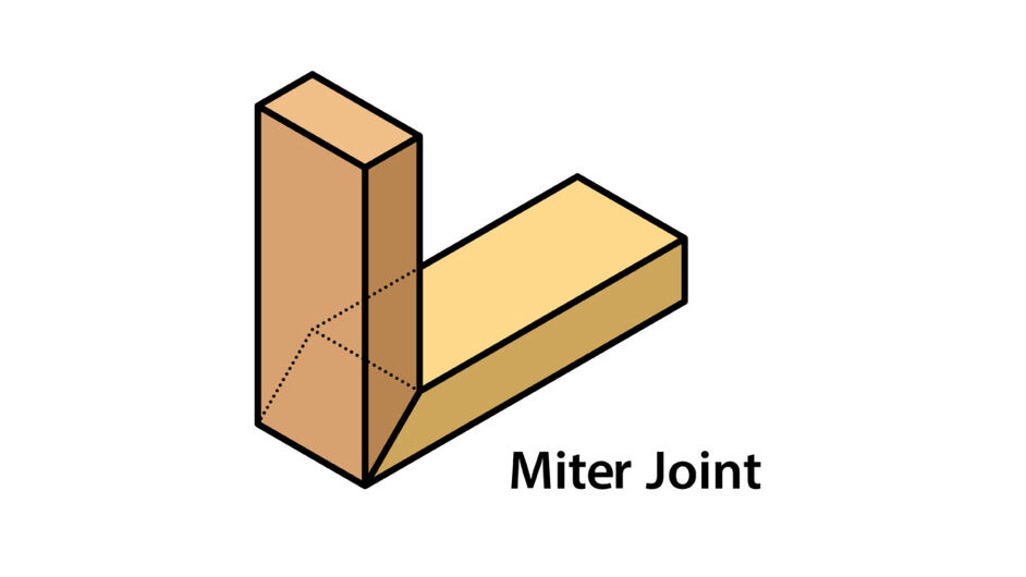
So, my goal was to create a 3D slicing method that would generate miter joints that would be at the correct angles of the 3D mesh and connect like puzzle pieces into a fully realized clean 3D object! This ended up being a much bigger challenge than I had originally planned for, but it was a great learning experience, and I wanted to share it here with everyone else.
From other forum posts I read, the only clean way to create a miter joint is by making a rig that your piece can sit on from an angle and cut straight through with the Glowforge. Two issues come from this. One is the focus. It is very difficult to focus on a single point of your piece that is not flat with the bed. This can cause multiple issues along the way as many of you probably know. The second issue is that it ties you down to just one single angle. This makes larger, more complex shapes basically impossible to create, and if you ever need to cut a larger piece with a sharp angle, you won’t be able to fit the piece in the bed without compromising on the size.
So, I decided early on that cutting was out of the question. The next option was the “new” 3D engraving that I had seen some people try to use. I tried engraving a gradient from 0 power to full power on different materials. Overall, the test did successfully engrave through, but it was also very much prone to catching fire or melting. This ended up being the biggest challenge when choosing a material that I could engrave all the way through while still retaining the joint. Since I was basically locked down into using full power on these engraves, I found that there was one big thing that led to burning or melting a material: the amount of time that the laser was in a single location. The LPI and speed both determined these and if the laser was too slow or had an LPI that was too high, it would immediately start destroying whatever I was trying to engrave through. I found that the best solution here was utilizing multiple passes. This did raise the print time substantially, but it was worth it for the clean engraves. Due to current pass limitations at 3, this automatically made any material over .125” thickness out of the question for this project.
I ended up settling on acrylic as my main material, both because of its strength and its consistency. If your material is made of a lot of layers of wood or paper, it will most likely not work for this project since the angle you are engraving can drastically change as if the resistance of your material changes through the layers. I found that MDF also worked well, but since we did not have an exhaust port for our Glowforge, MDF was banned in class since it would clog our filter. So, acrylic was my best choice!
Next was the angle itself. How would I calculate the exact angle of every plane of a 3D object?
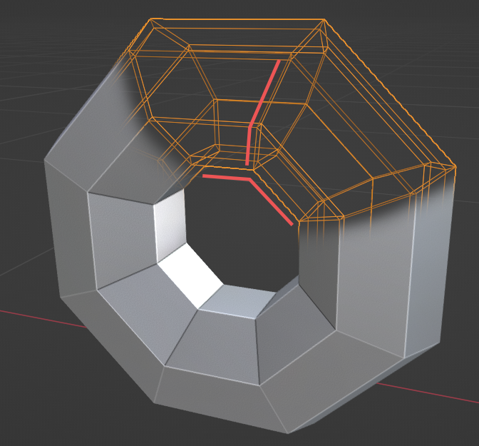
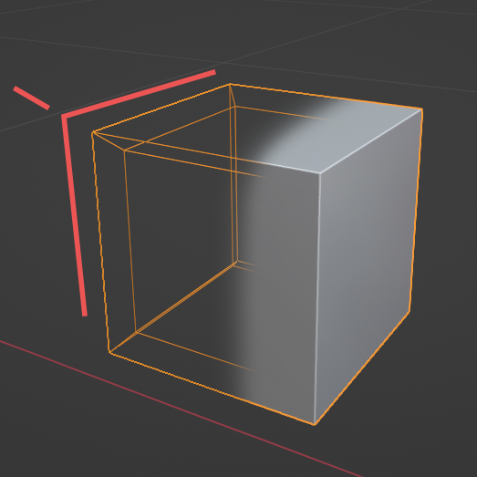
This ended up being a lot of fun and a perfect challenge for me as a technical 3D artist. I used Blender’s geometry nodes to add thickness to an object and “unwrap” it in a way that could be flattened into a 2D space for Glowforge to use. I had to get a little bit of help from some other Blender artists to finalize the process, but this generator ended up being one of the most fun things I got to create this semester! [Here is the file]
(https://1drv.ms/u/s!AkT_M95NR0GkoKt7eb3sDY_dXo34sw?e=8ee57O) where you can try it yourself if you want. Just be aware that you will have to have a little bit of Blender knowledge to use this tool. I would not encourage anyone without any prior knowledge to try it.
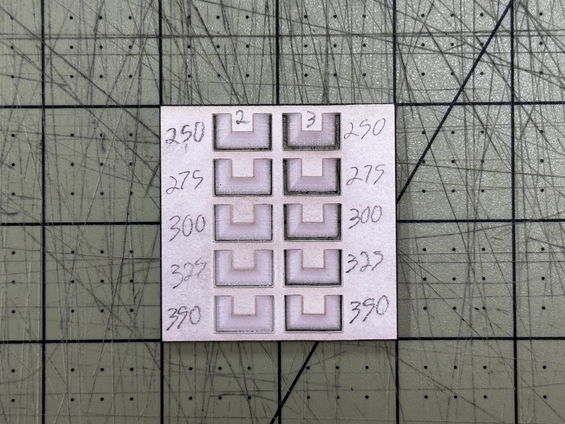
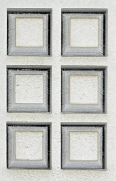
Before we start engraving any of the angles, we first need to find our most optimal speed, passes, and LPI that will engrave all the way through the material. I have a test here that is pretty good. You can assign whatever you think will work, but the goal here is for it to barely cut through along the edges of the wedge. If you chose one that has gone too much, your measurements will be misaligned, and if you chose one that is not all the way through, then the pieces will not be completely “cut” out in the end. For white acrylic, I chose 325 speed, 2 passes, 195 LPI. Keep in mind that with LPI, these areas will be inside our finished piece, so the detail of the slope will not matter.
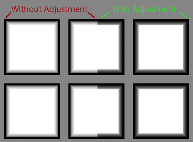
You might have noticed with that last test print though that the edges are not flat. If you have ever tried to engrave a perfect 45-degree angle with the Glowforge, you have probably seen this. It’s the bevel of the angle. If you try to just use a linear gradient from 0 to 1 on the Glowforge, you will probably immediately end up with a very convex beveled angle that extruded outward and makes the piece unusable when trying to assemble. I also solved this issue in Blender, but I needed a calibration test to make it work.
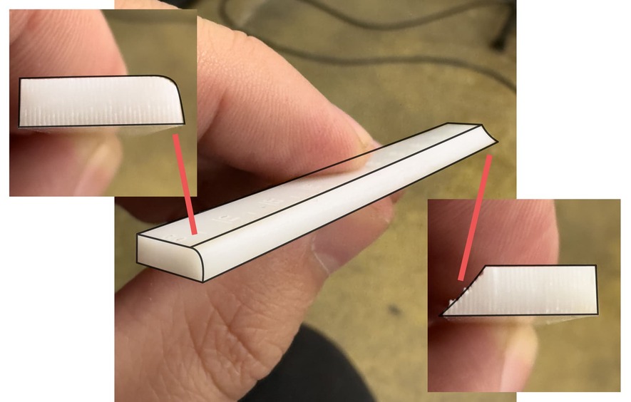
I made this small 45-degree test print that changes the linear curve from convex (Left) to concave (Right). It also cuts out a small compass tool that can help you measure the angle. This is all meant to counteract the initial linear gradient of the material you use into something that will be much straighter to work with. Go ahead and print this off with the settings you found in our last test and keep in mind that in most cases, the bevel should be concave instead of convex. We can fill in empty spaces with glue and fillers. We can’t do that with a convex edge. So, make sure to judge this print wisely and find the closest point that feels straight, flat, and not convex. You will see small numbers on the top of this test. It will be in decimals from 0 to 1. Pick whatever number you think looks best. For White Acrylic I chose 0.92.
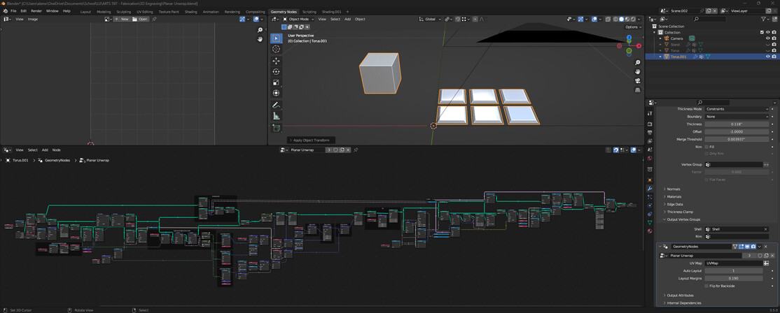
Next up is throwing our data into Blender to fix the angles and insert the proper material thickness. When you open the Blender file, you will see on the right side, we have two modifiers: “Thickness” and “Planar Unwrap.”
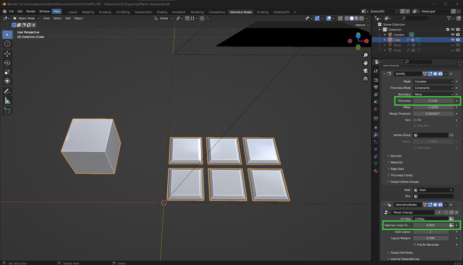
This is where you are going to put all your data. In the thickness one, just insert the thickness of your Glowforge material. Not too difficult. Next up, insert the number from your previous calibration into the “Optimal Linear Gradient” under the Planar Unwrap modifier. This will fix all the gradients on your model and make them engrave super clean.
The last step is creating your model. This is where prior knowledge of Blender will really be useful. Everything should be set to scale in the scene, so if you create a model that is 10 inches in height, the end result from the Glowforge will also be 10 inches. A couple of things to keep in mind with this tool: Your model needs to be simple. Do not grab a complex 3D scan offline and expect it to work. You will need to decimate and simplify your object into planes. Try and stay under 100 faces if possible. The highest I have gone is 56. Your model also needs to be manifold, which is the same as 3D prints. It can’t have holes in it. It needs to have faces all the way around the object.
As for the layout of what you are looking at, the middle is your viewport where you will see six pieces that are lying flat and a camera above them.
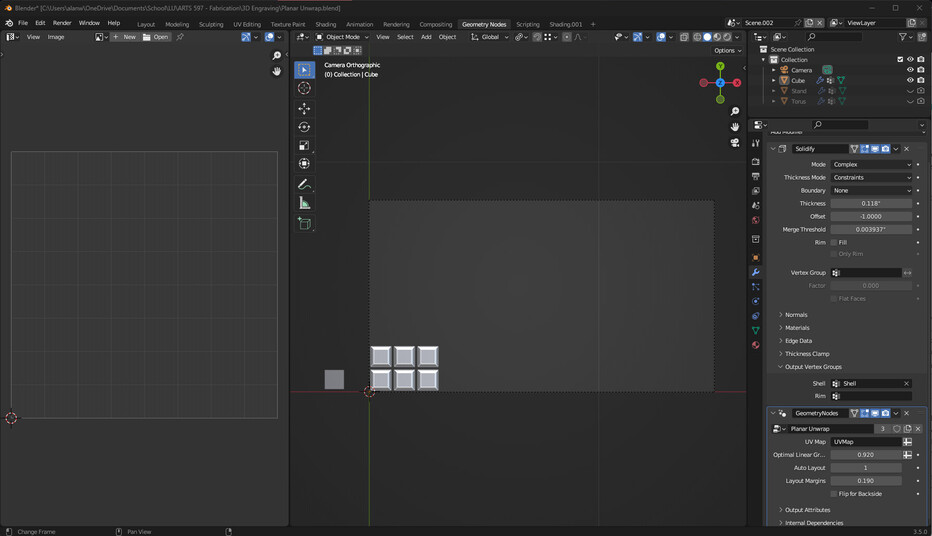
Imagine this camera as the Glowforge bed. It is 10”/18”. The left side is your UV unwrap settings. If you want to manually place each piece of your object somewhere inside your camera, you can go into edit mode (TAB), select all (A), unwrap your model (U + Unwrap), and then you should see your model all laid out on the left. You can select those faces and move them around in the UV editor, and you will see them also move in the viewport in your camera space. So, this is where you can rearrange each piece and determine how long this print will take. I understand this can be confusing, which is why I also included an “Auto Layout” selection on the right under the “Planar Unwrap” Modifier. It also gives you margins below that, which will determine the spacing between your pieces.
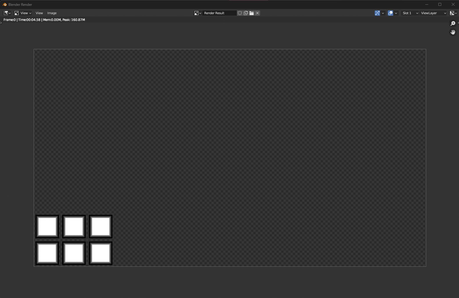
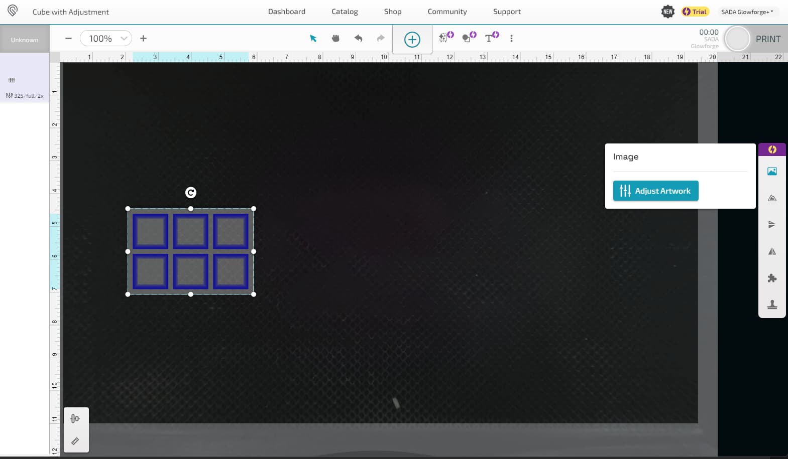
Now onto finally cutting out your pieces. Once you have everything laid out how you want, you will go to the top where it says “Render” and press “Render Image”. This will use that camera and render out the image we need to insert into our Glowforge. Once your render finishes (it will take time depending on your system), you should be able to press “Image” in the top left and then press “Save As” to save your image. It should automatically be 300 DPI, so once it finishes, now you should be able to just drag that image into the Glowforge dashboard add all the engraving settings we decided on earlier with our tests and start the engraving. Depending on your computer system and size of the model, this process can take a very long time, but it is totally worth it!
Ok, now for assembly. Once all your pieces are cut out, you can sand them down slightly and clean up some of the edges. Not always necessary, but it typically does make the assembly process easier.
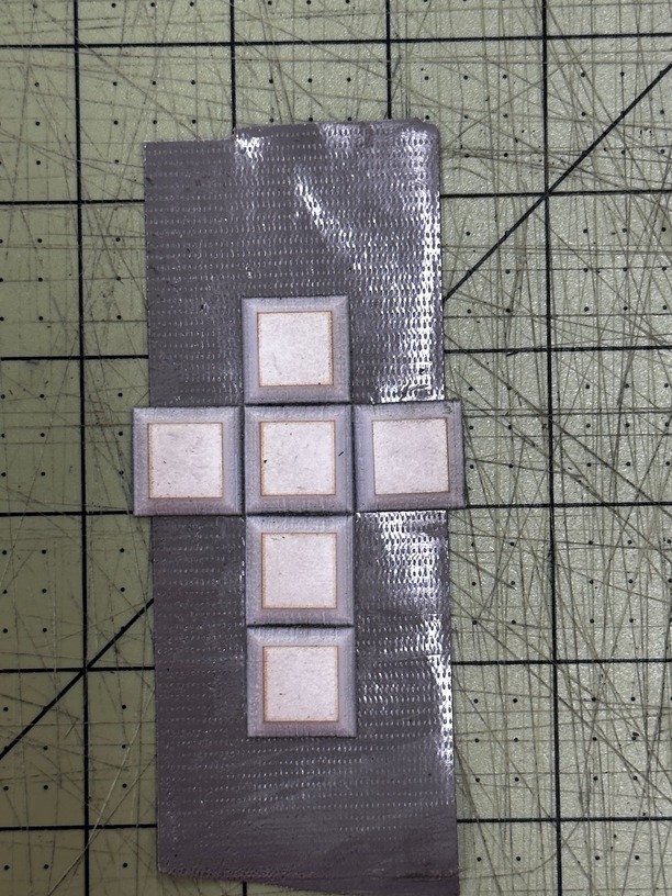
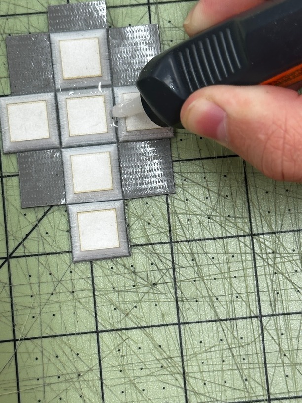
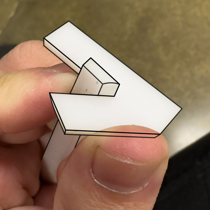
I like to use duct tape to secure my pieces together in the order that they will be folded onto each other. I then fill each miter joint with super glue or UV resin and use the tape to secure all the pieces together into their final form.
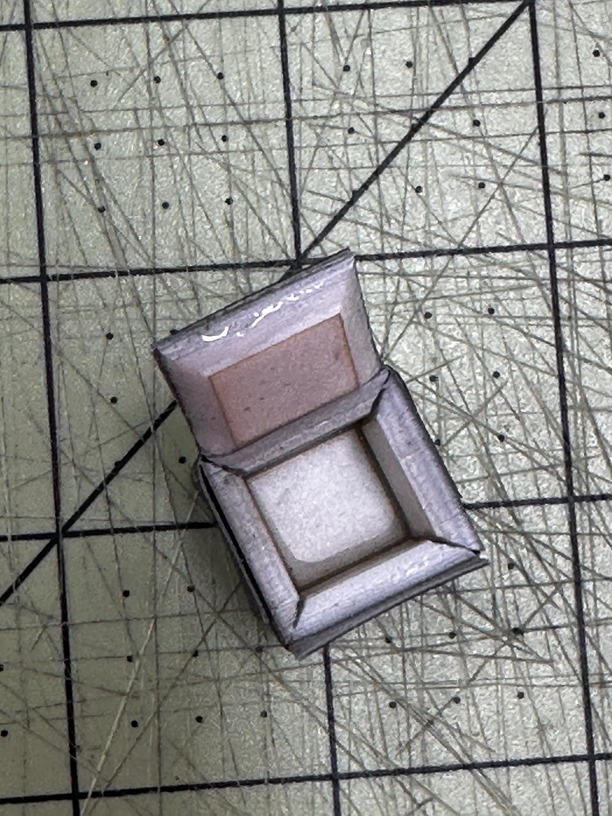
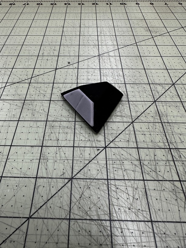
After letting it sit for half an hour, you should be able to remove your tape and see your “finished” 3D piece. Your first probably won’t be perfect, and you will want to experiment to find the best settings before doing anything too large. You might have some areas that do not completely fill in though much like 3D printing. The best solution will be using Bondo, wood filler, or wood putty. Basically, anything you can fill in with and then sand down will be the best fit for these areas. I recommend once you finish the sanding process and After letting the glue or UV resin sit for half an hour, remove the tape and you should see your “finished” 3D piece. (I spray painted the bottom of this piece of acrylic. It is white acrylic with a grey primer. Forgot to switch back to normal when I did this engrave.)
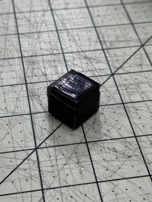
Your first attempt may not be perfect, and you may need to experiment to find the best settings before attempting larger projects. You may have some areas that do not completely fill in, similar to 3D printing. The best solution is to use bondo, wood filler, or wood putty to fill in the areas and then sand them down. Once you have achieved the desired level of smoothness, use some self-etching spray primer to give the object a nice finish that can be painted however you like.
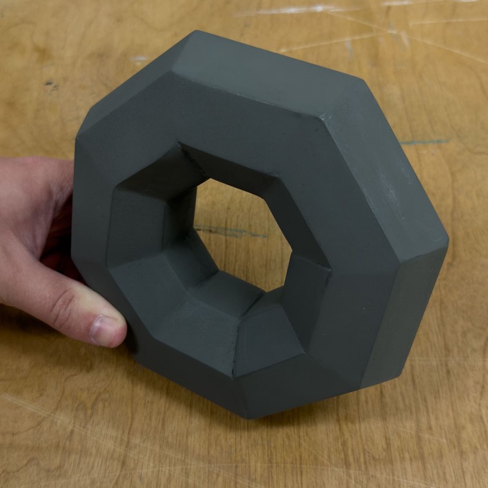
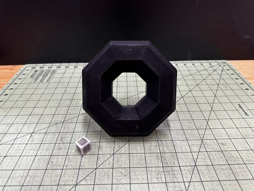
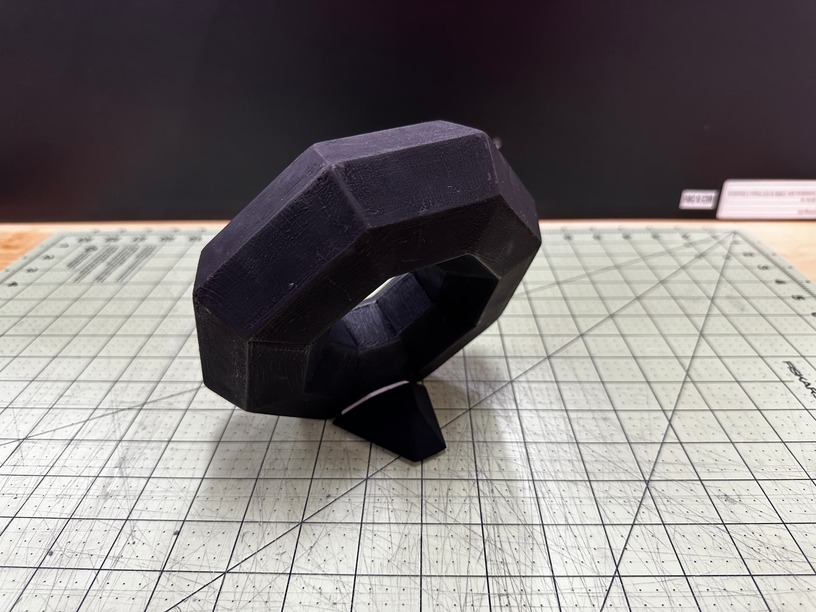
So there you have it! You can now create complete 3D objects with Glowforge using this method. I have already used this process to create a few different pieces mainly for testing purposes. I have a Torus Donut shape that is 7/7" and was my first real test to see if this method could work with large-scale projects.
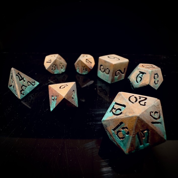
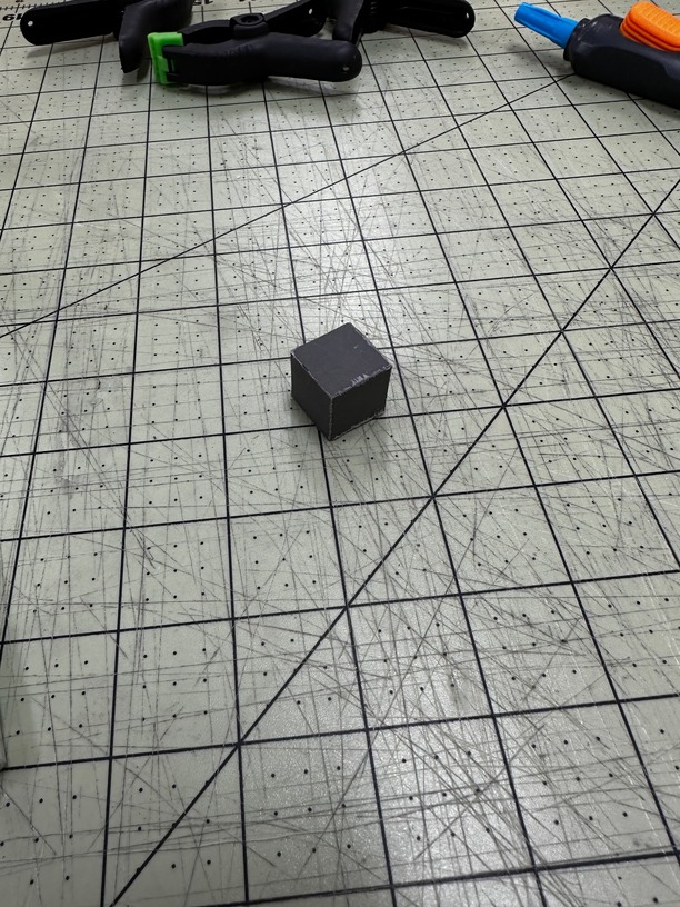
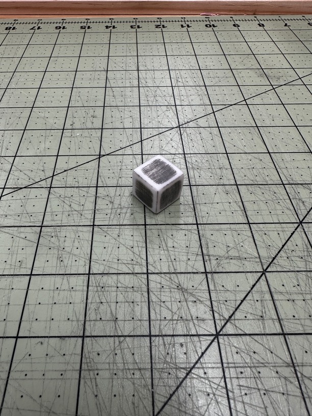
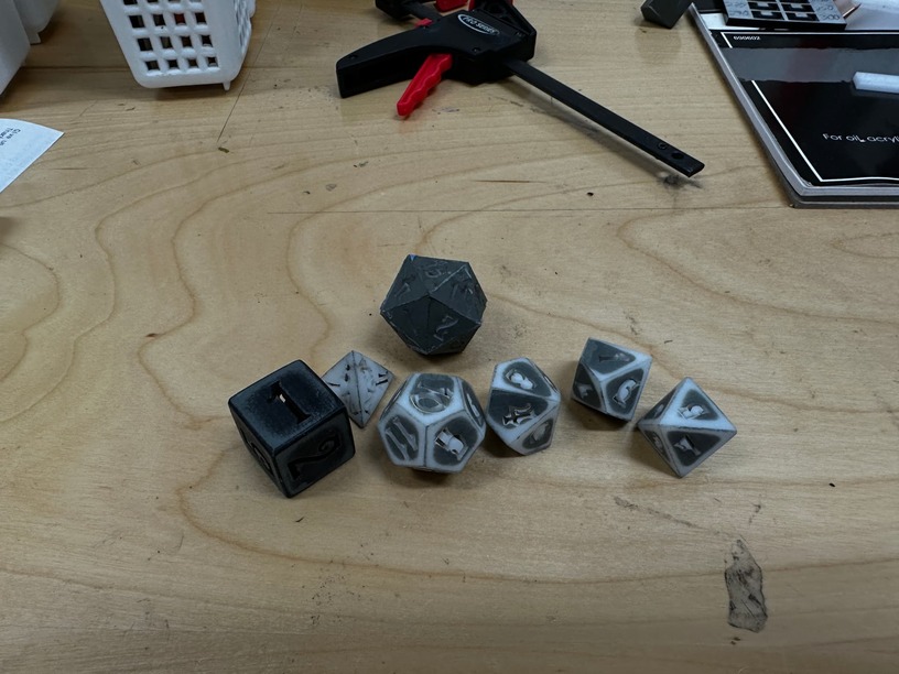
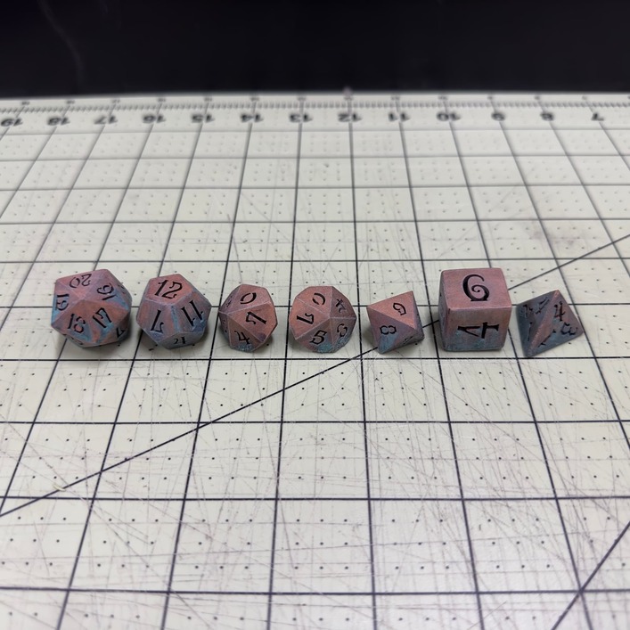
I also created a dice set. I didn’t plan the numbers and sizes out very well, so some are a bit off, but this was still just a test to show what could be done with this method.
I am super excited to see what others can create with this process! These files should work for you if you are using proofgrade white acrylic (with 325 Speed, Full Vary Power, Maximum Quality, 2 Passes, 195 LPI), but any custom shapes will take a few tests and blender knowledge to really make everything work. Let me know if you run into any issues or if you think there is a better way to do some of this. I would love to hear your feedback!
Notes for devs if you see this:
- More engrave passes would help make this process usable with thicker materials.
- Vertical and Horizontal pass direction would really help with consistency of engravings.
- Proper G-Code slicing where the laser treats engraving more like a cuts would help speed up engraving massively. So making it engrave by following the shape instead of just going back and forth over large blank areas.
(I completely understand some of these are requests are very difficult. Just wanted to share them.)