So I generally use locally source materials when working with my Glowforge and have a slew of my preferred settings saved locally. Very typical you say, however recently I’ve been becoming lazier. I’m tired of picking my settings when working with non-Proofgrade materials.
So I set out to make a plugin that could recognize custom materials automatically. With the hopes that I could just mask them, stamp them with a QR Code, and just like that they’d be recognized in the GFUI like real Proofgrade.
So forgive me for terrible video editing skills, I write software for a living would definitely not make it as a vlogger. Here is the first working preview:
Very cool. Glowforge really ought to copy that for the official software. (But alas they probably won’t, thanks to their friendly neighborhood lawyer.)
I’ve been meaning to add a select element to simplify that field for a while now. All I’m doing is computing the display value using the same formula that the GFUI uses.
The base values that are assigned to the select element in the GFUI are:
[1, 2, 3, 4, 5, 6, 7, 8, 11, 18, 39, 136]
In this case, I am manually entering the value 3. Which is subsequently converted to display value we see in the GFUI. Here is the raw code used in the GFUI:
  function hE(e) {
      return function(e) {
          return 5 * Math.round(e / 5)
      }(1 / (e * O.STANDARD_SCAN_GAP_INCHES))
  }
Loosely translated it says:
Get the scan gap for the raw value e, 3, in my case.
Multiply is by STANDARD_SCAN_GAP_INCHES which is a fixed constant of 0.0007381889763779527
Take that result and divide 1 by it.
Finally, round the result to the nearest multiple of 5
If you also look closely you’ll notice that they start skipping values when the scan gap starts getting really small.
One other thing that I’ve been meaning to play around with is having the ability to share an SVG along with a set of projects settings that remembers which layers have which settings applied. I think it’s possible based on that data that is available.
Standards defined by the industry, rather than proprietary values defined by GF.
Real talk though, I’m not sure what you mean here. There is only one set of values that can be used and they have to be the ones that are used in the material data model. Which technically are those used by PG materials. They are also the same ones used by the GFUI and the same values I compute. In the end all the values must be the same.
edit: What you see in the GFUI are not the real values, this is why it was such a big deal that it took so long to implement an inches toggle. The internal values are the same, only the display values change.
what i meant there was completely irrelevant, because my brain thought i was responding to a completely different post, so please ignore that. it’s been that kind of day.
so, back on track here. i asked about where you were pulling the values because of this thread here, where i first started to try to understand scan gap in context of GF settings.
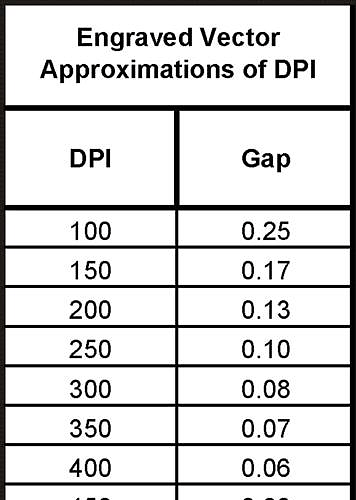
and in particular, in relation to this table:
if the formula you posted above is correct, then GF is claiming a fixed, constant scan gap of ~0.0007", which is very small.
so all of this leaves me a little confused still. is it possible that fixed constant number you posted has the decimal one spot too far left?
if the “about .008 in” number is correct, matching the scan gap (which seems fixed on the GF, if #2 in your translation is correct) would mean the proper DPI to set your photos (matching the #s in the table i posted above) would be 150. converting .008" to mm is .2032, which somewhere between the .17 and .25 gap in the table, but closer to .17, so let’s go with that.
To determine what DPI file to use based on the scan gap: 25.4 / scan gap = DPI
25.4 / 0.2032 scan gap = 125 dpi
and i’m still not sure this is right. this is part of what still drives me nuts sometimes with the lack of access to more specific (and industry standard) settings to work with the GFUI.
My best guess would be that it’s just a fixed constant used to fit their display values to a fix range between 0 and 1. Not that it has anything to do with how the motion file stores or the laser interprets the data as actual LPI/DPI/scan gap/GFPI…
which again, leaves me sad. because i can’t apply the information that owners of other laser cutters share from their experience in creating photo engravings on the glowforge because GF has their own unique way to handle settings.
It finally works! You can create your own custom materials and have the material automatically detected just like Proofgrade, both when you load the GFUI and when you open and close your Glowforges lid!
The biggest challenge over the last month has been a full rewrite of the extensions UI to make it more usable. I’m in the process of writing up some documentation and then I will click the publish button!