Discussion of June '17 update

What I am talking about is a way of addressing @palmercr’s wanting absolute positioning. Rather than a job-specific jig, a jig/guide that lets one repeatably go from design to proper positioning without guessing.

I selfishly hope you stick with it. I boxed myself into a corner with this adventure. You’re input is amongst the most valuable to me personally. On the other hand, I understand 100% why you’d bail out now. I still hope Glowforge is influenced (software wise) by your realism.

4 Likes

You take an oversize piece of plywood and butt it against either the front or the back of the machine. Make a 19x11 box centered on a 20x12 artboard. Send the box to the GF as a cut. Now as long as you put the shell piece of plywood in, everything you want cut to a precise space just has to be put in that place in the design program inside the 19x11 cuttable area. The front or back and sides of the GF are fixed reference points and your plywood outline will go back in the same space all the time (although you can just leave it there unless you need to mess with the crumb tray). As they make the cuttable area larger (it’s headed toward 20.5 x 11.5 if I recall), just create a new cut box centered on your artboard the size of the latest spec and cut it again. You’ll cut slivers out of your frame and have a new positioning guide.

4 Likes

Not sure when anyone has tried this last, but it does not currently work (centered, at least).

After fiddling around, 20 x 12 artboard, 19.490W X 10.990H box. From top left of your artboard, move it down .005, and .005 to the right. Centering does not work.

Someone with more time on their hands can probably refine that down a few more thou.

Center-Full-ArtBoard

1 Like

That’s got to be machine specific. I used that to do a few hundred pencils, souvenir coins, etc. But mine’s a PRU so may not represent the current state of the art and you’ve a larger W and an ever so slightly smaller height specified. I haven’t bumped mine up to the 19.5 dimension because I don’t think my machine can do that as I ran into an issue when I went over 19.

I do believe we had some folks mention their left & right margins were different. Might be a case of needing first to print a series of lines to see where your machine’s margin is so you can tune it to your device.

Though, I just ran this on some painter’s tape I put on the crumbtray. The head hit the front door down in the right corner.

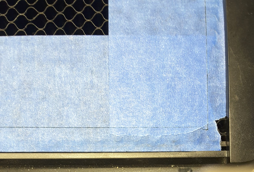
Caused the head to pivot off the magnet mount a bit, and redirected the laser forward. It was traveling from back to front at that point. When it traveled to the left, it snapped back into place.

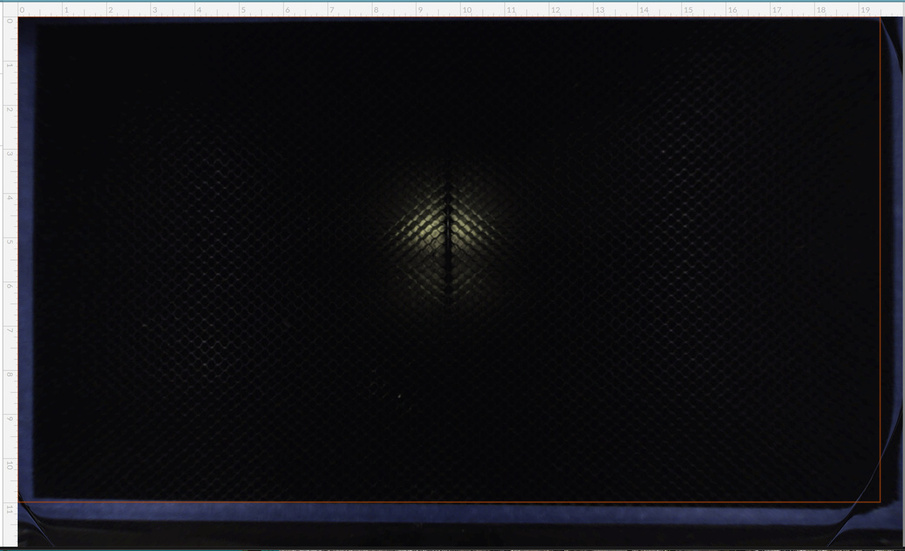
At least now I have a nice visual indicator on the crumbtray to tell me where the cuttable area is.

Too bad it doesn’t match up to the GUI:

2 Likes

Whoa, that ain’t right. I assumed the whole reason the UI prevents us from placing cuts close to the edge is to prevent that from happening. I would say this is a serious bug if it can cause the machine to damage itself.

3 Likes

It could have just been out of alignment. Ill power cycle it and run it again.

Not to add to the pile of horse carcasses, but limit switches are very effective at preventing over travel in situations where the unit is no longer calibrated.

Super sensitive accelerometers in the laser head could, in theory, accomplish similar things.

1 Like

When the head parks at the back it is completely out of the camera view. Is there room for it to travel to the RHS while being at the Y park position? If so they seem to be wasting a large amount of possible cut area. The camera seems to be a bit too far forward because it can see the back of the front door.

Not being ably to cut the full 12" width of the material is a massive disadvantage.

1 Like

I lost 2 huge jobs to this problem before I found out what was causing it. I now have a stack of a hundred incorrectly engraved tokens. I will no longer run jobs to the bottom of the bed, I was hoping this was just a PRU issue. Im sad to see that it is not.

4 Likes

Which side is the bottom? The door side?

Yeah close to the door

After a power cycle, and calibration, it is still doing the same thing.

You can see the head hit the door when it reaches the end of it’s Y move, and then it appears to tip back to normal after it begins the X move.

Here are the witness marks on the head:

Here is the result of the bump on the cut:

As a side note, of little importance: I did about 10 power cycles yesterday testing repeat-ability of the homing process (around ±.004" on my machine, not bad…). And the sequence was: Y-move to center, 1 or more (this varied from 1 to 3) X-Moves to center, quick adjustment jump to center, X- to left, Y to rear.
Just now, it was X-Y move to near center (single move), quick adjustment jump to center, and the normal return to rear left. So, it appears there may have been a cloud software homing sequence change between then and now.

2 Likes

Hey Scott, it may be good to repost this in #problems-and-support.

Shhh… The likely outcome of that will be less usable space. :wink:

Like @takitus, I’m just avoiding that very small area. It’s about 1/4" sq. in. out of 214 sq. in. of usable space. Plus, they have clearly stated in numerous other threads that the usable area is a work in progress.

1 Like

Collisions are definitely bugs and we would love to hear about them. It won’t damage your machine but could ruin your print.

3 Likes

Well it has caused cosmetic damage, see the marks on the head. Why don’t the accelerometers in the head detect it?

And if it rotates the head isn’t there the possibility the beam will miss the entry window and etch the coating off the side of the head?

It’s probably in the hopper.

I’m not being sarcastic, I really mean that they have probably thought about it but not yet made it a priority to implement. Clearly they are behind on the software on many fronts.

Except that Dan showed us all a video showing it working. Note the tense: https://www.youtube.com/watch?&v=nvYu7Vbx2oM