Like @Dan, I launched F360 for the first time in a while and was utterly baffled by the new UI. My old workflow (create sketch, export as DXF) seems gone.
Great excuse to check in and see what the cool kids are using.
And the answer is: Colorific! Lots more info here: New Workflow from Fusion 360 to Glowforge. In particular, take the time to watch @secret_sauce’s video. It is long, but chock full of useful information and very clear explanations as to why things are done certain ways.
But not quite enough info for someone completely clueless like me to get started.
Specifically, the video shows how to take a single flat object and run it through colorific. I was baffled by getting the thing installed and then figuring out how to turn my multi-component 3D contraption into SVG files. Like, say, a box.
So, some notes:
Install Colorific
-
Go here: GitHub - garethky/glowforge-colorific-fusion360-post
-
Download the GlowforgeColorific.cps file.
-
Make sure your Cloud Libraries are enabled in Fusion and upload * GlowforgeColorific.cps* to your cloud account. Full step by step documentation is provided here: How to install a cloud post processor in Fusion 360
(I initially tried a local upload. That didn’t work. No idea why. The Mac client makes figuring out what the heck is up terribly difficult.)
Create a New Cutting Tool For Your Glowforge
-
Switch to the Manufacture workspace in Fusion 360
-
Under Manage, open the Tool Library.
-
Click the Pew Pew icon (Laser cutter).

-
In the description, enter the name of the material you are creating the cutter for! This is because the kerf is different per material and, thus, you’re going to want to build up a library of materials with custom kerf settings.

-
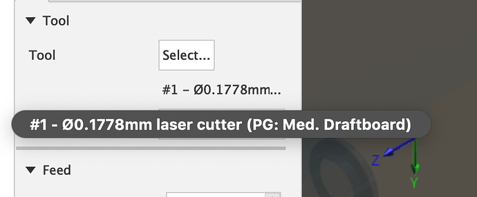
On the Cutter tab, select Laser and enter the kerf.
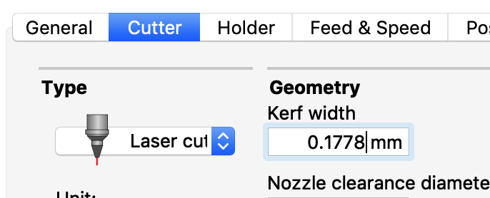
Ignore the other fields and tabs. They aren’t used when targeting a Glowforge.
- Click OK.
Anyone gotten around to building a Tool Library full of settings? It’d be easy to do and then we could just import from that.
Setup the Cutting Path Generation Environment(s)
This is the way I achieved success. It definitely works. I suspect that an F360 expert will point and laugh at what follows and, hopefully, tell me I’m wrong and there is an easier/better way.
When you do this, F360 will create cutting paths in the X-Y access. So, when dealing with a 3D model full of components in various orientations, you will need one setup per each component’s orientation. Think of a box; it has 6 pieces, 3 sets of parallel pieces. So, for a box, I create 3 setups where I set the orientation such that the Z axis is perpendicular to the face of one set of parallel pieces.
-
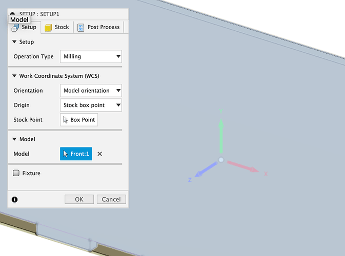
In the Milling tab of the Manufacture workspace, select Setup → New Setup.
-
Select the component(s) that you want to cut for the Model property.
-
Set the Z axis to be perpendicular to the face of the component you want to cut. In this case, the Z axis was correctly oriented.
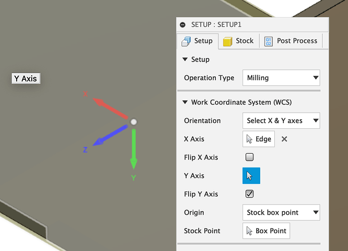
3a. When setting up the end, I used Select X & Y Axes and then set the two to an edge. I messed with the flip until the Z axis was pointing to the “top” of the piece to be cut (the Z axis effectively points at the laser).
- Ignore Stock and Post Process; aren’t used.
Create the Cutting Paths
-
Switch to the Fabrication tab in the Manufacture workspace.
-
Select Cutting → 2D profile.
-
Select the laser tool you created earlier.
-
In the Passes tab, select Left or Right Sideways Compensation and set the type to In Computer.
This is the magic bit that does the kerf (thank you to @secret_sauce for the clear explanation). You can turn off kerf entirely by setting it to Center. The “in computer” bit is because we aren’t directly controlling the GF from F360 so F360 needs to apply the kerf compensation prior to export.
-
In the Linking tab, turn off both Lead-in and Lead-out. The Glowforge cloud takes care of this for us.
-
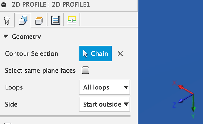
In the Geometry tab, select the component that you want to cut. Note that you can select the component or you can select the edges to have more control by creating more cutting operations.
-
Click OK. Under your setup, you’ll find a new 2D profile. Clicking it will show you a preview of the path generated.
Use Colorific to Export SVG
-
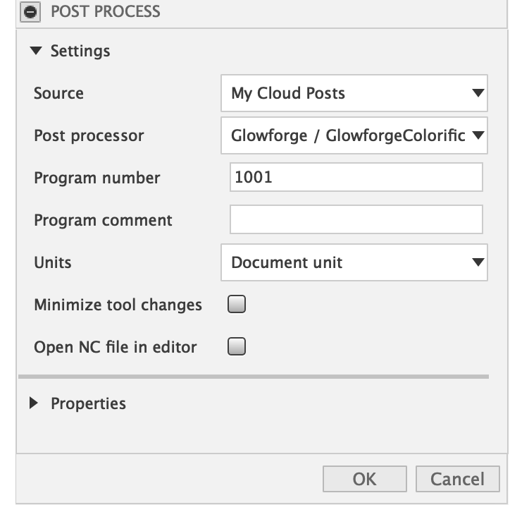
On the Milling tab in the Manufacture workspace, select Actions → Post Process.
-
Select the Glowforge / Glowforge Colorific post processing plugin.
-
Click OK.
-
Name your SVG file in the save dialog and save it!
Done.
