Gear and/or belt slippage?

I’m experiencing a consistent failure when using the Cut function on my GF Basic. The issue (as best I have been able to determine) only occurs when cutting complex shapes on the “upper” half of the cut bed.

Notes:

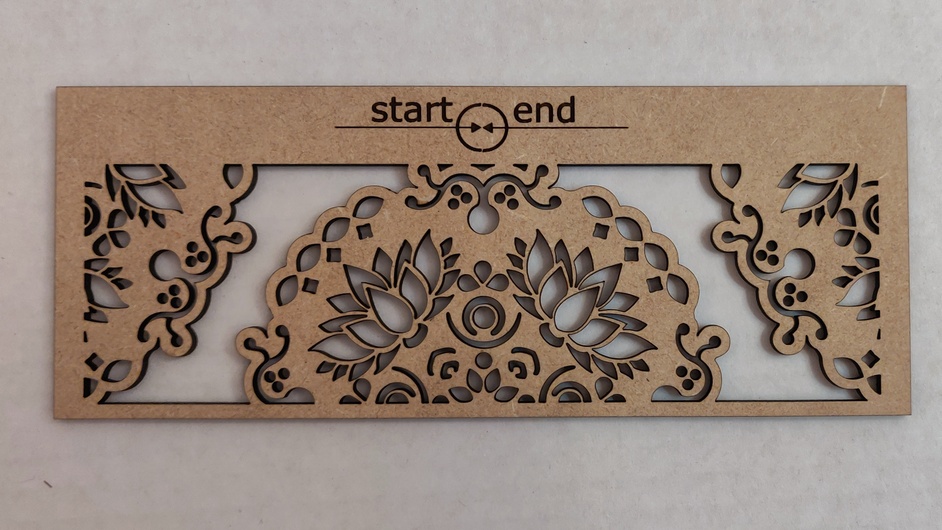
  • I denoted “start” and “end” Score lines as tasks at the beginning and the end of the list of steps in order to track the degree of shift.
  • The complex images segments are the only pieces set for 2 passes.
  • I separated the top and bottom shapes into different tasks to ensure that the shifts during 2 passes were relative only to each independent task.

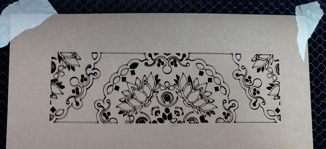
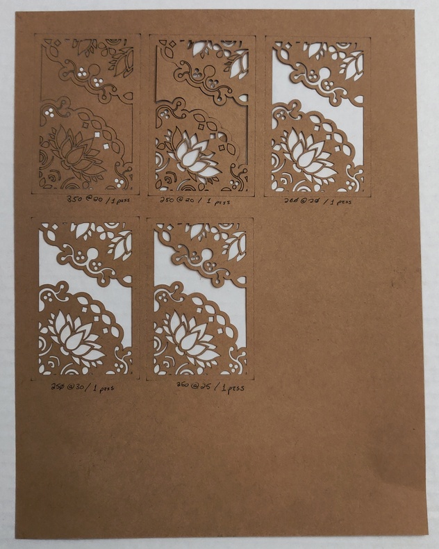
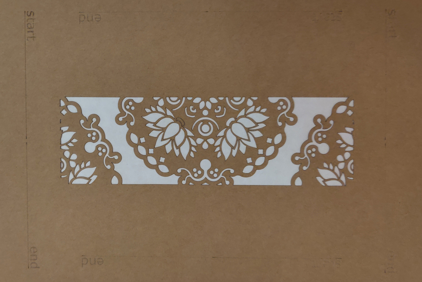
Here’s a diagnostic cut.


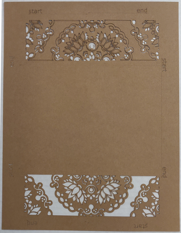
The top half of the overall job is a train wreck. There was an occasional audible “thunk” as the head shifted forcefully. No such instances (as best I could track while watching the job) occurred when the bottom image was being cut.

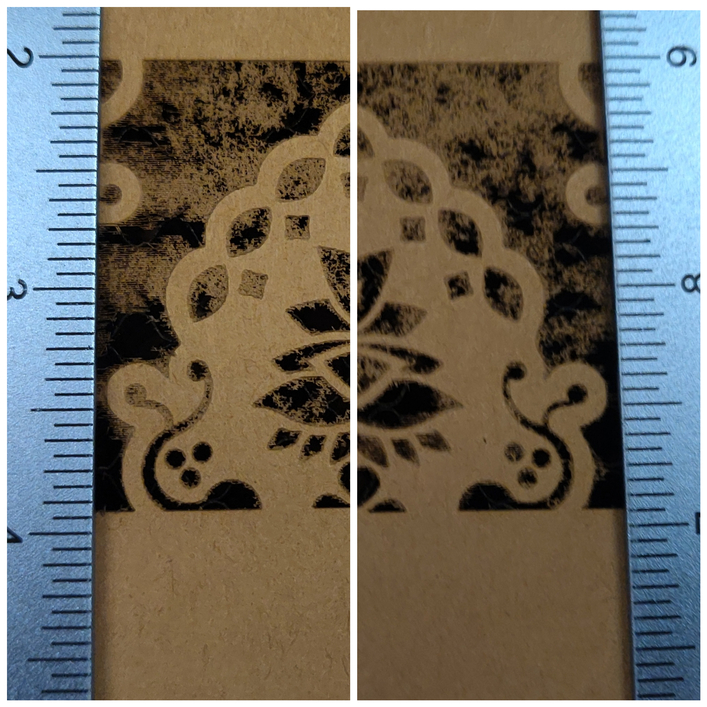
Here’s the closeup of the top segment.

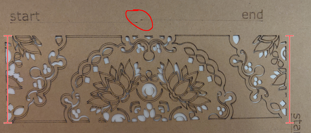
  • The start/end lines are not aligned.
  • There is a massive amount of disparity between the first and second passes.
  • The shift has dramatically altered the height (relatively speaking in relation to the photo orientation) of the left edge versus the right edge of the graphic.

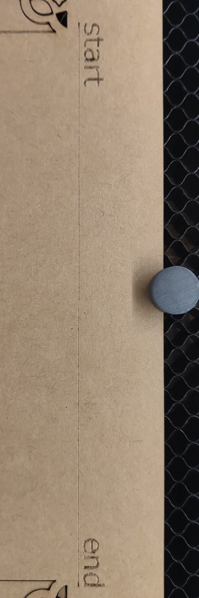
Here’s the bottom edge.


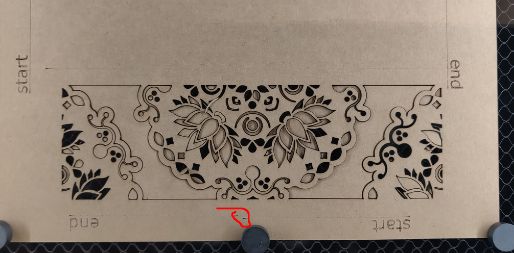
No noticeable affect to the graphic itself. The diagnostic start/end show the impact to overall positioning, though.

Left edge. Mild start/end offset in comparison to the top/bottom, but still not what one thinks of with “laser precision.”

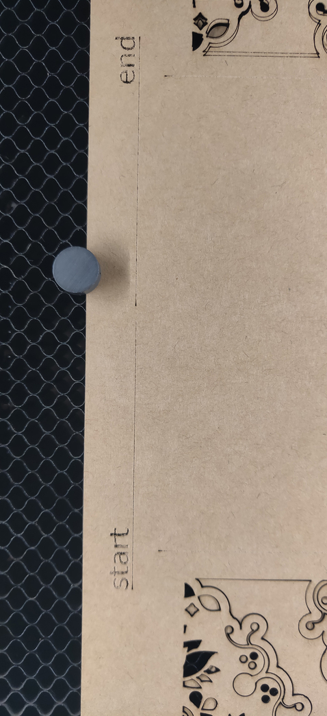
Right edge. Also mild variation for start/end.

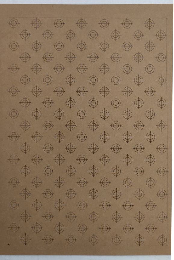
Here’s the kicker. It only appears to be with the Cut task, or with complex shapes (or a combination of the two). I made the below “crosshairs” calibration test with the following tasks:
*All score lines
*Only the crosshairs themselves (“+”) had a 2 pass set. There was no discernible shift anywhere from top to bottom.

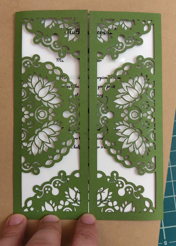
Here’s another diagnostic cut. Same graphic, but in a landscape orientation, and with the page docked closer to the bottom edge of the crumb tray. As best I can tell, nothing was off in the resulting cut.

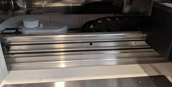
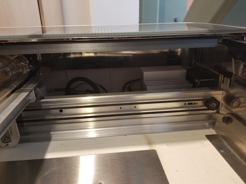
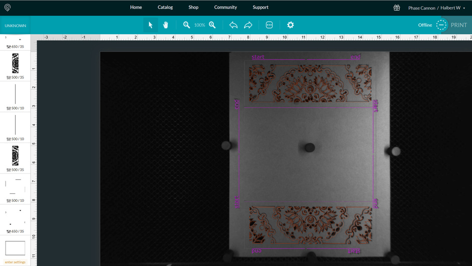
And, in case it’s relevant, here’s a screenshot of the print bed after the cut.

What I’ve done so far:

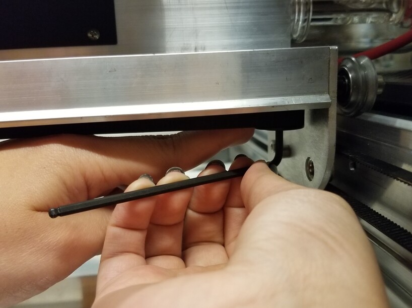
  • Performed the cleaning steps as spelled out in the guide.
  • Attempted the “perfect squares” step in the Troubleshooting pages. But that doesn’t seem to have any impact on subsequent tests.
  • Created and tested the above diagnostic tasks.

So… What do I do? I’m unaware of anything further I’m even permitted to do without voiding my warranty.

Couple of things it could be:

A thunking sound is generally indicative of the head hitting something somewhere, and once it does, the rest of the cut is going to be off.

To check, turn off the machine and grab a flashlight…slowly move the head left and right, forward and backward by hand and see if you can feel when it happens. If the thunking always happens at the back of the machine…look for problems with the left and right belts as well. (Going to see it when moving the gantry forward and back.)

Second possibility - those magnets look tall. Strong magnets can interfere with the function of the head…either get some flatter ones or try just taping the paper down to the grid with masking tape. You do need to affix paper because the air assist can shift it.

1 Like

I had the same thought. Even though the issue was happening only on the upper region, and magnets are present at all areas (I’m thinking, if it happens in one place, I expect it to happen in all places), I’ll do another cut with just tape to be certain.

Thanks for the quick reply! I’ll run a shorter test of just the upper graphic, in the upper half, (with tape) since that seems easily reproducible.

No luck with tape. (I can’t even look at this result without feeling like I’ve got double vision.)

Also:

I can’t reproduce any “catches” by hand. It only happens during a job when in motion for the cuts.

I see a couple of things…

This is a “cut”. Why are you making two passes? I agree that a second pass should line up perfectly and these do not. But why two when one ought to do?

If I look at the offset on the left, it is clearly bigger than the offset on the right. It almost looks as if one pass is slightly rotated relative to the other, where maybe the lower right corner is the pivot. I can’t think of a way that a bad stepper motor or belt could do this. Since this is a “cut”, the X and Y motors are stepping forward and backward continuously. If the motor was missing steps or a belt was slipping, it should be doing that continually, too, and the result should look like spaghetti.

In addition, the issue is repeatable. It does the same thing every time you try it. But it didn’t do it with the crosshairs test pattern, which easily covered as broad an area. Are you sure this isn’t in your artwork?

Not to sound argumentative, but this is my primary issue with most support forums. The question of “why are you doing ‘x’ when ‘y’ would do?” is completely, technically, irrelevant.

Even if the response was, “because redundant tasks are the only joy in my life.” the root issue would still be present. As for the actual “why”:

  • If I do a single pass at higher power, I get a full cut, but I get char on the finer segments. It also helps by not requiring me to put down a new backer sheet time after time to prevent flashback.

The settings I’m using have been dialed in and tested a godawful number of times at this point.

You and me, both. But then, I didn’t design a multi-thousand dollar precision plotter. I only purchased it with the expectation of consistent results. I love this thing. It’s performed amazingly on the tiny stuff I’ve done so far. But something is failing and I’m just trying to find out why.

Stepper motors, nor the belt system, are that complex at their root. But something appears to be - technically speaking - all jacked up. Is there some sort of tension system that might be at play with the belts? Like, one side too loose/tight, perhaps? Then again, that begs the question again of just how much we’re allowed to touch internally on our own.

Correct, it didn’t occur with the crosshairs. But there are two key differences with that file:

  1. As noted, it was only a Score task for each component. I don’t know if there’s an internal differentiation regarding the motion control there, but I was certain to note it just in case.
  2. Also noted - the crosshair pattern is comprised of simple shapes (circle, circle, line, line). There’s no sharp cornering mid-path for any lines (which is where my head keeps going back to with the complex patterns).

As for my artwork, I’ve checked it, I’ve deleted it, and I’ve recreated it. I always get the same job results, despite the fact that it’s a graphical mirror (left/right in the job’s orientation). And since it’s the exact same image on the bottom, I trust that the file content is being accurately interpreted by the GFUI.

If I cut the bottom half only, then flip the paper, rotate the artwork (for consistancy of content), and cut there’s no issue. But I can’t rig a jig to be reliable enough to pull this off for 50+ cards. And, again, I shouldn’t have to by the nature of the device’s intended functionality. I just wanna use the whole (well, minus those border buffers) cut bed.

The only reason I’m at this impasse is because originally (earlier in the week) I was finding that my perfectly parallel lines (according to the x,y coordinate values of the individual points) were not folding flush after creasing at the score lines. As I was troubleshooting it, I rotated the entire piece into a portrait orientation to see if the I got the same folding issues. And that’s where I discovered all of this behavior.

As an additional flavor, I converted the artwork to a .PNG and let it Engrave (well, with my ignorance of the best dialed in numbers) with the artwork placed in the same “upper” half region, with no slippage behavior. But then, with an Engrave, it’s a series of straight passes back and forth, so again, no sharp cornering.

One problem I had some time ago was that when the machine was moving fast the change in direction was equivalent to a bump, and a bit slower and lower power solved that issue.

3 Likes

@rbtdanforth I was wondering about that, too. It’s at 500 speed currently. I’m still too new to this to know if that’s considered “fast” or not.

My only concern about changing that is the fact that it only occurs on the top half of the bed. The bottom copy of the same graphic was always pristine as best I can tell.

1 Like

If it makes a problem it is too fast, like driving the speed limit on an icy road or the doctor joke. “Doc, it hurts when I do this!”’ “Don’t do that then” a lot depends on the design. It would not take much for there to be just enough more “give” in the front of the machine to act as a shock absorber. It would very much be tied to the design specifics.

I am more sloppy in this but several folks here keep a detailed journal of every run, what speed and power, and what was the result, and they solve problems faster than I do.

1 Like

When there are sharp turns in a design leading to thunks, I turn the speed down to 250 or 200 and adjust power to compensate. That or fine-tune the design to subtly eliminate the sharp turns.

3 Likes

Definitely agree with the “rounding or cutting the sharp curves/tight corners in the design” suggestion, as well as the “slow things down a little” suggestion for complex vector work. When you do slow it down, reduce the power too. (Any kind of mat will prevent char. A Seklema mat is highly recommended if you plan to do a lot of paper work. You can also get rid of the magnets if you use one.)

One other thing that I noticed in your top pictures…you have apparently rotated the design on the bed - when you uploaded the file, the decorative bars ran vertically, not horizontally. Nothing against that, it should work perfectly if you rotated it correctly, but user error is pretty easy in such cases, so it could also be a factor.

(I’d personally start by placing a cut in the sharp corner of each leaf/petal. That forces the start and stop point for the beam on that shape, and we used to have to do it with digital cutters, which drag a knife that can hang up in corners that tight.)

It might just very well boil down to the design itself since you couldn’t find any mechanical reason for it with the initial testing. Which would definitely be a good thing. It’s the cheapest thing to fix. :smile:

2 Likes

Thankfully, I’ll not have to budget that into the process. This is a one-time thing to make the wedding invitations for my friends.

I’ll slow it down more and see what that yields. Hopefully that also addresses the lack of a square cut that started all of this.

Thanks to all for the suggestions!

2 Likes

It looks like you’ve already received some guidance from some of our other community members. Thank you folks! You’re correct that the expected result for a two pass score process should be for both passes to be aligned.

After trying the suggestions from the other community members, are you still running into the same trouble? If so, I’d like to take a closer look at this for you. I extracted the logs from your machine and the motion path for this print did not include the offset seen in the results. Because of this, would you please do the following to check for any mechanical issues or debris which might be causing the issue?

Here are some steps to follow:

  • Turn off your glowforge
  • Remove the Crumbtray
  • Examine your unit of any debris on the floor or in the teeth of your motor belts.

After checking the above, would you please send me the following photos?

  1. A photo of the belt with the laser arm pulled to the back of the printer
  2. A photo of the belt with the laser arm pulled to the front of the printer

  3. A close up photo of the pulleys at the back of the printer on both sides

Once I have those photos I will follow up with your next steps.

Thank you!

@ivan1

As requested:

  1. Laser arm pulled to the back.

  2. Laser arm pulled to the front.

  3. Closeup back left.

  4. Closeup back right.

1 Like

Just in case a ProofGrade test is suggested, here’s a straight pass of pure PG material and settings.

  • Material: Proofgrade Medium Draftboard
  • Engrave for text and arrows: SD Graphic
  • Cut for main pattern: Proofgrade Cut

I didn’t change any settings since PG is typically a simple straight shot as far as configurations go. Plus, the whole concept of an established baseline of performance / expectations.

There’s obviously no double pathing scenario with the main vector since PG Cut is a default of one pass. The alignment markers for the start/end are ever so slightly still out of alignment (and yes, I’ve verified three times that the cut file points in the vectors of the arrows are aligned).

Since the shift in alignment is notably less so at the much slower speed of the PG Cut settings, I’ve gone through with some much slower speeds on my paper cut attempts with close enough squaring up that I should be able to finish the invitations that started me down this path. And hey, I’ll finally have my first post content for Beyond the Manual after all of this is said and done. :wink:

@ivan1 If anything comes from the inspection of the requested photos, please let me know what, if anything, you all need from me next. I don’t know what the Glowforge acceptable margin of error is for precision on the devices, so this may be something I just have to deal with.

And thank you to all who have been chiming in with helpful feedback!

2 Likes

It is a beautiful design,

1 Like

Thank you. It’s been a learning experience from end to end. I’d not realized just how rusty I’d become with Inkscape - and I wasn’t even proficient to begin with.

1 Like

Thank you for the detailed photos as well as the update on your test on Proofgrade material. I agree with @rbtdanforth; this is a very lovely design!

When you re-ran your print on the original material using a slower cut speed, did you run one or two passes? Would you be able to provide a photo of the results using the slower cut speed? I reviewed the photos of the inside of your unit and didn’t see anything which looked out of place. One other thing to check would be the tension on the belt below your laser arm. Below are our standard instructions for this process.

Please do the following:

  1. Turn off your Glowforge.
  2. Carefully remove the crumb tray.
  3. Without removing the carriage plate and belt, locate the black pulley fastened by a metal screw on the right end of the laser arm.
  4. Insert the short side of the 3mm hex L-key into the metal screw with the long handle pointing toward the front of the unit.

    ​​
  5. Turn the key clockwise to loosen the screw until the pulley can slide with some friction. Don’t remove the key from the screw.
  6. Holding the key with your right hand, use your left index finger to push the pulley to the right until the belt is taut. Don’t stretch the belt or touch the belt with your fingers as this can affect the tension on the belt.
  7. Applying firm pressure with your left index finger, turn the key counterclockwise to tighten the screw. Make sure the pulley doesn’t move during this time.
    ​​​​​
  8. Continue tightening the screw until you can’t turn the key anymore.
  9. Gently slide the carriage plate from side to side to ensure it moves smoothly and the belt does not catch or sag.
  10. If you’re not satisfied with the tension on the belt (it should be taut, but the belt shouldn’t be stretched), go back to step 4 and try again.
  11. If you are satisfied with the tension on the belt, try a test print. Print the Gift of Good Measure on the Proofgrade Draftboard we included in your material shipment for troubleshooting, and let me know how it goes!

This GIF shows how much motion you should normally expect when pressing on the belt with your fingertip:

If you have any questions or run into trouble along the way, don’t hesitate to reach out! I’m happy to help.

5 Likes

Yes, @ivan1, will do. I didn’t upload the preliminary tests because I had written my testing data on the cardstock and didn’t know if that was something that was restricted purely to Beyond the Manual. I know that there are rules in place for unofficial data in order to respect liability concerns, etc.

With each test, I restricted myself to one pass since, if there is slippage going on, two passes would allow for double the degree of shift (relatively speaking). Since paper is still, well, paper, I stood by with a fire extinguisher within reach, as well as a dampened handkerchief - just in case.

I found two settings that seemed to play well. One of which left me with virtually no need to weed, so I did a full cut with that configuration and had something passable. The final invitation is bulky enough after adding the inner pieces that the slight misalignment was negligible.

I’ll go buy a hex set tomorrow and perform the recommended tension tests.

2 Likes

Just following up.

How have things been looking since your adjusted the tension on the belts?

If this has been resolved, great! Let me know and I’ll close the thread.

If you’re still having trouble, the next thing I’d be interested in is tracking down something you mentioned:

There was an occasional audible “thunk” as the head shifted forcefully.

I’m wondering if you could get a short video, so I could see and hear the thunking.

You can post it here, or upload it, and send a link to support@glowforge.com .