HOWTO: Kerf Measurement and Jig

Understanding the interaction between your tools and materials is critical to making parts that fit well. A key metric to understand is kerf: the amount of material removed by a cut. Compensating for kerf is the difference between joints that are sloppy or that fit with just the right amount of force.

Even though a laser cutter removes only a fine amount of material, that slight difference in dimension between your plans and the physical material adds up. It’s worth noting that your kerf can vary between batches of the same material, power and speed settings, and over the lifetime of the machine. Because a laser beam is only in focus at a specific point, the kerf also varies throughout the thickness of a cut.

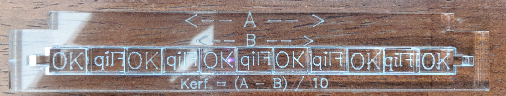
Here’s a jig you can use to measure kerf (right-click, save as):
kerf%20tool

It works by comparing a reference length (A) to the length of a set of blocks (B) which have been cut from the same stock. That difference, (A-B) is the sum of the kerfs of each cut. It’s much easier, and more accurate, to measure this compound kerf than to try to measure the kerf directly by cutting a square of known size.

Assemble the jig

Each block has OK or Flip engraved on it. This allows us to compensate for the vaguely trapezoidal shape of the blocks due to divergence of the laser beam. We’ll flip every other block left-over-right. This example is made with Proofgrade Thick Acrylic to show you how the jig should be assembled. You’ll notice that the Flip marks are backwards and on the bottom of the block when inserted into the jig.

Measure the reference

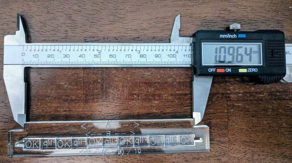
If we had an ideal cutter that could make perfectly planar cuts down at the molecular level, the reference portion of the jig and the blocks should have exactly the same length. We’ll start by measuring length (A), the top-most width of the jig. You should take several measurements and average them together.

Measure the blocks

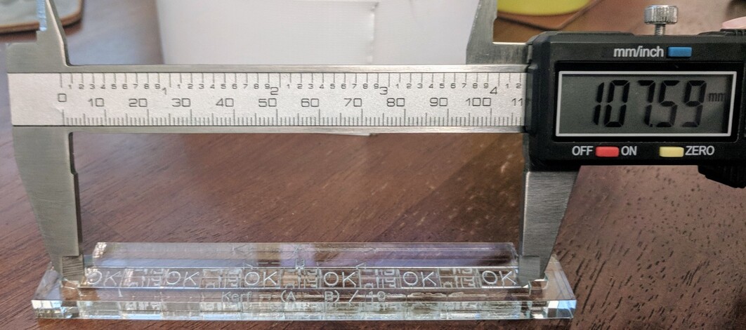
The jig has a couple of cut-outs to make it easy to insert calipers to measure the width of the blocks. Again, you should take several measurements and average them out. If you’re feeling adventurous, you can measure the blocks outside of the jig.

Compute the kerf

In this case, my average (A) value was 109.64mm and (B) is 107.5mm. This gives us (109.64 - 107.5) / 10, or .214mm / 0.0084in. This is a starting value that I’ll use, adding an extra thousandth of an inch for joints, or subtracting one or two thousandths for clearances. Please note that the acrylic used in this example shrinks slightly when laser-cut and will have a larger kerf than wood or other materials. In general, though, you can expect your kerf to be a few thousands of an inch.

Additional reading

90 Likes

I think I’m missing the obvious here, but you have 11 blocks, and that is 12 kerfs ?
John :upside_down_face:
On second thought A has a kerf missing at each end - is that it ?
Or 22 half kerfs across B, and 2 half kerfs across A !

1 Like

It’s a “fencepost” problem: If you want to build a fence 10 yards long using 1-yard beams, how many posts do you need? Eleven.

This jig assumes that the reference edges and the edges of the two outermost blocks are co-linear. Since the same amount of material ought to have been removed, we don’t need to think about the outside kerfs. This leaves us with only the 10 cuts that separate the 11 blocks.

11 Likes

Ah, but my explanation shows how confused I get.
Time for a cup of tea, I think.
:upside_down_face:

5 Likes

Nice! Thanks for sharing the file. :grinning:

2 Likes

Over the years I directed the day to day work of hundreds of engineers and programmers, and folks that had PhDs in Math or Physics. There was one Physics PhD that was brilliant but communication between us was almost impossible. He thought in abstract terms and I did not. Had to assign another engineer to be a translator between us.

For my simple mind… The first measurement already includes the two outside cuts so there are 10 additional kerfs to average.

8 Likes

Very nice jig and write up.

Just a couple of thoughts from earlier conversations and personal experiences.

I love the DFX to Laser plug-in but I’ve come to prefer adjusting for kerf right in Fusion 360. This way I get total control over what compensates and what does not.

Also, while your jig most likely gives very good numbers ( I love the /10 thing) I find that differnt typs of joints make a difference so I tend to play with a sample joint to get things fitting just right.

Anyway, thanks for sharing this. It definitely adds to the conversation.

8 Likes

i always do this. i try to figure kerf. then i make my box in boxes.py. then i snip out a section of both sides (maybe 2-3 fingers) and cut that out of some sample of the material and make sure the pieces fit. and if i’m off in my kerf, i go back to boxes.py and adjust the number slightly and try another sample joint. it’s tedious, but even when i think i have kerf right, my real world sample can be either slightly too tight or slightly too loose.

6 Likes

I’ve also noticed this. Thought I had settings dialed in, made 20 copies of something, and they all fit together a little differently.

3 Likes

that’s because of this:

and even the same sheet can vary in thickness from one end to the other.

4 Likes

Well, thank you for this—looks very useful!

2 Likes

This is a great tool - am going to cut a few of these very soon!

Now, just one thing that’s confusing me is whether to use this value or this value / 2… Probably a stupid question…
But if the value I get is, say, 0.17, do I then enter that value in laser CAM settings in Fusion 360? Or do I enter half of that value?
Same thing for those box makers - those reference to “kerf / 2” which is what’s confusing me…

1 Like

I use the full value in the Fusion CAM workflow as the size of the laser tool. What you’re measuring with the jig is the amount of material removed by a cut and the box generators that I’ve seen also ask for the full-value kerf.

3 Likes

Clearly I’m not too smart. I’d love the jig, but cannot find where to download it! Thanks

1 Like

It’s in the OP. Just right-click it and save it.

2 Likes

Oh! Thank you (sheepish grin)

3 Likes

Finally learning how to adjust for kerf. Babysteps but this jig helped so much on reducing the learning curve

Thank you!

15 Likes

goodness, I have read your post about 5 times and I really wish I could understand it. I know what kerf is and I’m slowly learning, but I wish you posted a quick video on how to use this jig. Usually I can pick up on things quickly but this kerf thing is really messing me up and I am trying to work on a project with slots. I don’t understand why I can’t just add 0.2 mm more to each slot. I heard that is the size of the beam. Is it because the laser size varies between machines or because the laser beam size changes depending on material, speed, power, etc? I suck at this kerf thing man!

2 Likes

Adding 0.2 mm more to each slot would work, if that was the actual kerf of the material. Finding the actual kerf of a particular material is the tricky part, because the size of the beam is only part of the equation. It’s burning away material, and how much gets burned away is what really matters, not the size of the beam that did the burning. This tool lets you find the exact actual kerf of the individual material you are working with, so you know exactly how much to adjust your tabs and slots to compensate. :slight_smile:

4 Likes

Yes the kerf changes with material, speed and power.

4 Likes