If the camera can detect edges, position of material on the bed wouldn’t matter. Even angle wouldn’t matter. The software could just adjust x and y planes accordingly. And if it registers incorrectly, we should be able to manually specify x and y planes simply by dragging lines on the screen.
2 Likes
So you don’t necessarily have to have a physical margin, like an angle of two sides to butt material against. You just need something that touches off zero on the surface of the material or bed? Or you just enter the coordinates in because the head already knows where it is in relation to the limit switches?
1 Like
With my mill I drill holes in the MDF waste board and screw 3D printed L and I pieces in three corners. I then know exactly where the sheet will end up and shift the origin to that.
I also have wigglers that I can use to touch off an arbitrary placed object to find its edges.
3 Likes
That’s the key - the frustrated folks are that way because of their history with a particular solution to the problem of precise placement and repeatability so it gets expressed in terms of the solution rather than the problem. I have that issue with my team all the time - either they or the client say “we need to do this thing”, not “we need to solve this issue” so they’re coming to the table with solutions posing as problems and that boxes in their thinking. We have to work at saying “what’s the issue or use case we’re trying to address” and then we can figure out ways to address it and the solution that’s best often isn’t the one we see everyone else using.
I understand both views because I’m used to the defined 0,0 on my other lasers (and 0,0,0 on the Shopbot) but I’m open to alternate solutions to the problem.
13 Likes
I[quote=“jamesdhatch, post:84, topic:8716”]
We have to work at saying “what’s the issue or use case we’re trying to address” and then we can figure out ways to address it and the solution that’s best often isn’t the one we see everyone else using.
[/quote]
This is exactly it. As I learned from a great friend and teacher in a more social/relationship/ life structure fashion, it is “Essence vs. Form”. A method to establish exact coordinate location is the Form, but what is truly being sought is the Essence of ease of placement for their jobs. We often think a particular Form is what we want, when in truth there is quite often a number of forms that will lead us to that Essence. 
2 Likes
It depends on the project. Could you describe the use case you’re concerned with? I’ll give you the state of the art now (and we have lots of improvements in the hopper for later).
1 Like
That is some of the best news Ive heard in a long time! This will save sooo much agony, and allow for so much more precision! I know its not final, but im going to say thank you now just because its such a relief to even hear that!
6 Likes
May I suggest consideration only up to the point where the answer is “Yes.” ![]()
1 Like
Sure, I’ll use the same example I’ve used before, that of a steel ruler. Unlike the GF one:
- This one’s markings start at the very edge of the material on 3 sides, and;
- It’s made of a material that the GF cannot cut (so we have no bleed to cut away like with timber).
Example: https://www.jetpens.com/Kokuyo-Stainless-Steel-Ruler-15-cm/pd/11291
Oh, and we want to fill the bed with them.
Looking forward to hearing how to best tackle that one without a known 0,0?
1 Like
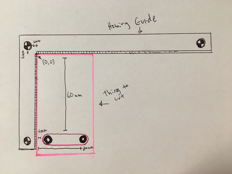
I think the answer here is that we will have to build our own 0,0 jig. Its one of the main things I am wanting to accomplish first when I get my prod unit. This along with numeric positioning will allow me to skip making a jig for so many things, as it will basically be a corner in the top left to push everything into and measure against.
4 Likes
Is the goal to engrave an existing blank ruler? If so, I would create a file like this:
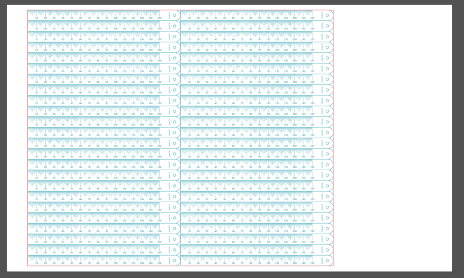
then put a full sheet of inexpensive material down on the bed, with magnets or tape to hold it in place (depending on the material). I’d load the file. I’d set the teal engrave step to ignore. I’d cut the red line. I’d pull out the center piece of material and lay down the rulers as shown in the ‘hole’. Then I’d set the red line to ignore and the teal lines to engrave.
We have other ideas for how to make this even easier in the future, but on the rare occasions I’ve needed more accuracy than the camera can provide, I’ve found this approach to be only an extra few minutes of effort.
14 Likes
It is.
I like this and if it’s all we’ve got right now I’ll take it…
A few downsides:
- There is a bit of waste on the bed dimension because we’d have to leave enough margin for rigidity of the jig;
- We’d have to go through the process EVERY time we want to engrave a set of rulers.
- There is material waste (cheap or not).
- We’d have to find a way to hold down the jig very securely - a few strong neodymiums would probably suffice;
But… It looks like it will provide one of the key functions we need. If you could improve it to allow for repeatability that would be a next level functionality for the machine.
Hopefully, we’ll get this feature one day:
8. Optical Alignment
The dual cameras align the laser head with the frame, with your design,and with your material. Glowforge realigns with every cut and engrave, adjusting timing and position, so every print comes out perfectly.
8 Likes
Thanks @takitus, however, the problem is that the GF can’t seem home to an absolute 0,0 position… relative to the frame / gantry. I think how it works is that the lid camera reads the head position (logo?) and then determines its origin point. Problem there (as I understand it at least) is that it happens every time a job is started. And if there had been any movement or play on the axes over time, the 0,0 could be in a slightly different place every time. However small this difference may be, it’s a problem when precise alignment over the bed area is required - in a repeatable manner like with the placement of a jig.
1 Like
Yeah, you are correct, and I am really familiar with the issue and have been a big proponent of a 0,0 for a while now. I previously proposed a fiducially marked corner piece that would serve this purpose by allowing the head camera to triangulate itself based on the 3 fiducials on that corner piece. (was on the thread you started)
12 Likes
I’ll likely do the same - if only because that’s what I’m comfortable with. But it’s funny - I was working on the Shopbot last night and moving it using the jog positioning function and thinking that it would be nice to be able to just drag and drop the project on the board ![]()
It’s going to be all about specific use cases I expect but I’m getting more flexible.
1 Like
oh i totally agree, we were cutting out foam pieces for my GFs armor last night, and drag and drop was a lifesaver. I never would have been able to do that on the K40. Its definitely one of the reasons that pushed me in the direction of the GF, but I really am going to need precision placement for a number of projects, and lining it up to scores on the tape I put in the bed is really not what I want to be doing forever. It leaves too much margin of error.
You’ve got me thinking of using the back wall of the Glowforge to affix a jig to. I have been using the front and an edge of the crumb tray for pretty good alignment of a jig and using cardboard. Trying to do some rulers and having more exacting standards is making me rethink it. Some type of jig that I can register on the back side of the Glowforge, perhaps using a bunch of rare earth magnets to keep it fixed and use one of my acrylic framing squares as the corner jig.
2 Likes
i wonder if an interim step might be a grid overlay that you could snap things to within the gf ui. it would cover the full cuttable area, letting you consistently put things in the same place each time. i’m not sure if it’s easy to put material in the same place each time, though.
1 Like
Aye, im sure there will be some blueprints at some point. I am going to have to make one just for the fact that the crumb tray has so much play in it. It will probably be a situation where the crumb tray will sit in this large more snugly fitting piece that has 0 play. attaching to the back wall magnetically will probably be essential, and will provide additional support for the passthrough slot on pro units as well.
1 Like