So I decided to draw up a visual guide. Something like this would be incredibly helpful. Basically its an L shaped ruler/square with 3 registration points. If the glowforge could read those points it would know exactly where it sits in the bed, and its orientation, and where the corner is that we can align objects against. Then if we can enter an offset against that corner location for our cut to be made, it would give us the desired accuracy.
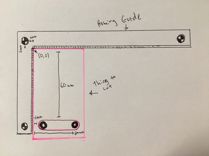
For example in the drawing below I want to cut the 2 black holes in the template (pink box) ive made on my CNC machine. I know that they need to be 60mm from the top of the piece, and 4mm/30mm from the left. I know that the top corner of the material is now aligned with the homing ruler and glowforge now considers the top left inside corner of that 0,0.
I load a circle svg into the UI and tell it to move the top left corner of that svg down 60m and left 4mm from the 0,0 point glowforge has ‘generated’ based on the location of the homing ruler. then im good to go. Rinse and repeat for the next hole 30mm over.