Template to NOT measure the kerf (test directly for tightness instead)

The common way to adjust for kerf — start by measuring the kerf with calipers, then make test cuts and adjust until you find the right amount of tightness — involves unnecessary trial and error.

Instead, these templates let you directly test a range of pre-applied kerf adjustments. The increments are small enough that you can usually find 3 or 4 adjustments that fit, but with different tightness.

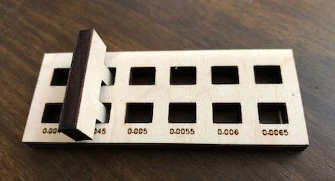
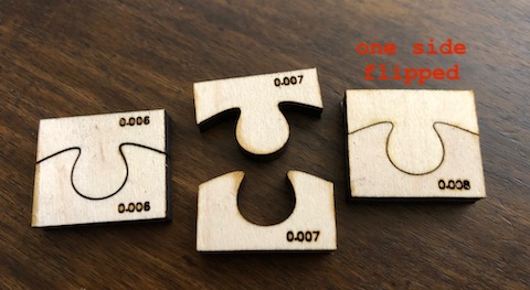
There’s one template for edge joins (e.g. jigsaw puzzles), and another one for box joints (or tenons).

In theory, both templates will give you the same answer for the kerf, but in practice, :point_right: you don’t actually care about the kerf, you care about the tightness. Tightness has different behavior in jigsaws vs. box joints. And the relation between tightness and kerf varies depending on the material (e.g. acrylic vs. soft poplar wood).

IMG_5322

For edge joins where you plan to flip one piece upside down, you can test this by flipping over one of the jigsaw pieces.

IMG_5321

For inlays where you want the inset to be raised (protruding from the surface), you can test that too. A tighter overfit gives a greater protrusion.

The numbers indicate the amount of hypothetical kerf (K) in inches; your design will typically make an adjustment of K/2 on each piece (or else K on the first piece, and zero on the second).

To use the templates, set the numbers to “Score” and everything else to “Cut”.

:warning:Do not change the size of these templates or the calibration will be incorrect.:warning:

kerf-adjustment-jig-edge-joint

kerf-adjustment-jig-box-joint

Here’s an alternate, more compact version of the edge joint tester, with both metric and imperial measures, which fits along one edge of the cutting area. The first file has them as separate pieces, and the second file has them in a zipper:

tightness-test-compact

tightness-test-compact-zipper

42 Likes

This will prove very helpful. Thank you.

Would you consider moving this to the Free Laser Design category?

12 Likes

I was going to put it there, but that category doesn’t allow the tag “kerf”.
But yes, the design is free for anyone to use.

12 Likes

Nice share, thanks!!

10 Likes

Even with the volume of prior art I like your take on the kerfinator and will give them a try.

12 Likes

Yeah, I know, I find it really hard to make sure somebody hasn’t already posted something similar. I’m sure somebody has, if not here then elsewhere on the web.

15 Likes

I’m more a fan of the comb-type. You can print them out of different materials and dial in the kerf on both at the same time.

7 Likes

That’s cool… :slight_smile: Always, different solutions will work better for different people… and in your case it’s obvious from your Finger Joints post that you know what you’re doing! Those joints are really nice.

Regarding joining two different materials, for these templates you can print the mortise sheet from the first material and the tenons from the second material.

11 Likes

Thanks for sharing! I’m sure this will be very helpful!

7 Likes

Sorry I was moving too quickly yesterday and didn’t elaborate. I generally prefer comb style but I wonder if this would be a better test for inlay (the puzzle pieces especially).

There’s something to this where you’re sort of testing in two dimensions, the comb/slot style only lets you dial in kerf adjustment for material thickness, this method might be better for the complexities of an inlay piece. Interesting.

10 Likes

I love these. I have been using both the comb type, and the 10x cut type, but neither really satisfied the way I think about designing. This does.

I made some simple modifications to your file. FIrst, I color coded it for the GF (all text one color, all internal cuts one color, all external cuts one color), then I added in a 0 kerf to the jigsaw shape, I created metric versions, and finally I place the link to this thread.
kerf-adjustment-jig-edge-joint imperial

Many thanks.
kerf-adjustment-jig-box-joint imperial
kerf-adjustment-jig-edge-joint metric
kerf-adjustment-jig-box-joint metric

11 Likes

I’m getting more confident in my ability to use Inkscape. I had no problem re-creating your 0 kerf jigsaw design, for example. But I am still not good enough to have made that design with the nice, symmetric smooth curves. Can you explain how you went about it in whatever SW you are using?

5 Likes

I can’t speak for the OP, but here’s some very good advice about using bezier curves:

I’m a big fan of using guides to lock bezier handles to cardinal directions, it becomes very easy to make smooth even curves.

As for symmetry, just draw one half and then clone the half, flip it horizontally and snap the nodes to the original. When all is done you can unclone it and merge the two snapped nodes to make it a single path.

9 Likes

@stoli , I use Affinity Designer. I did exactly what @evansd2 said (locking bezier handles, cloning & flipping).

5 Likes

Without locking the tangent horizontal, copying and flipping would leave a cusp. I never considered using guides for the handles; that would address one of my stumbling points. Thanks.

5 Likes

Thanks for doing the metric version!

3 Likes

Another thing to consider when doing kerf adjusted inlays is that when offsetting a path the accuracy of that offset can be dependent on the number of nodes you have in your design. Curves are mathematical approximations, and sometimes the process of offsetting can introduce errors. You can improve the result by adding more nodes to your final design prior to offsetting, as described here:

6 Likes

Improving kerf adjustment on complex shapes, post:1, topic:50465"]when doing a “stroke-to-path” action on an irregular shape, you can sometimes see deformation of the resulting paths. The solution: add more nodes.

Thanks for that tip! Unfortunately my templates were done with very few nodes. I don’t know if Affinity Designer does a better job than Inkscape.

3 Likes

I don’t see a download link.

2 Likes

Right click on the design and “Save as…”

4 Likes