The cutting board is .5375 inches thick.
I think my measurements are all messed up. A user error issue for sure.
The cutting board is .5375 inches thick.
I think my measurements are all messed up. A user error issue for sure.
OK. Take the tray out. Use risers of about 1" and use the set focus tool. All good then.
I can’t get the entire print in there if I back it up from the front near the door. If I move it back then the top of the artwork is out of bounds on the top. I can’t get an 11" artwork to print without resizing it once I import it.
Going to give this a try.
Thank you all for your help and helping confirm I’m an idiot!! ![]()
I think you’ll find that once you get the cutting board up into the correct range for printing, the resizing problem is going to go away. Try to find something about an inch thick that you can set it on.
The actual height cut is just under 11" more like 10.9 "
To be clear I am talking about front to back the available distance is a hair under 10"
So for an item (cutting board) that is .9055 inches high, does it need anything under it when I remove the tray?
I’m just not understanding why and when anything is needed under an item when the tray isn’t used. If the machine measures the distance from itself to the material why does it need something under it.
Thanks
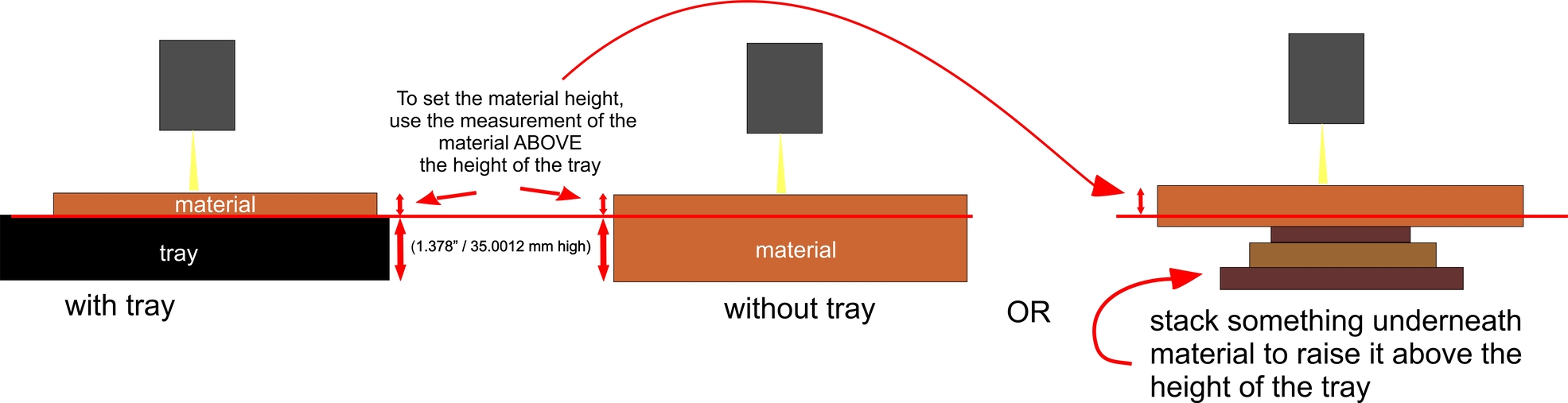
It’s because the laser can only focus within a certain range. The top surface of the item to be engraved has to fall into a range from 1.4" to 1.9" (as measured from the surface of the metal plate in the bottom of the machine without the tray.) Or the laser can’t focus on it and the measurements are going to be very wrong. So you have to prop up smaller items to bring them into that range.
We used to have to do that manually, now you just have to make sure that the top surface of the item is between 1.4 - 1.9 inches from the metal plate in the bottom.
Here’s a visual of what Jules is describing. Like other cameras, the GF has a focal range you have to be in for it to work correctly.
In a nutshell, the laser lens is a 50mm Focus lens, meaning the beam comes into focus 50mm away from where the lens is. To be able to focus on items of varying height, the lens moves up and down inside of the head to achieve that 50mm distance.
Since it can only move up or down so far, that is what necessitates the need for the material be in a certain range.
Other laser systems mostly have a bed that moves up and down that is used to adjust the distance between the focus lens and the material. The Glowforge doesn’t have a moveable bed, but opts to move the lens up and down to achieve the needed distance.
Ok. I thank you all for your patience and explanations. I have read a lot in these forums and I still get confused at times. What you are saying makes sense.
So here is what I want to make sure I am doing correctly.
I have a new cutting board in the machine (14x11), the tray is removed, I have one of these risers I printed and assembled underneath the cutting board. I am using the -.50 riser.
https://community.glowforge.com/t/various-height-bed-risers
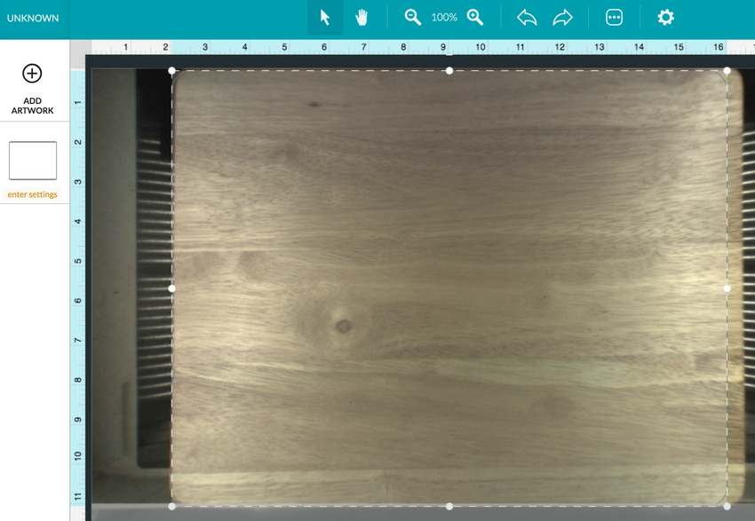
This is what the GF presents me with when I close the door.
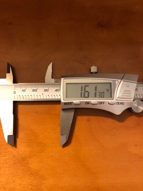
This is very close to a test rectangle that I created to see where the boundaries are for the 14x11 piece of material. I understand that it doesn’t quite get to 11" so I’m ok with that. It’s not getting the 14" width of the board. So is this because the measurements are off? I have not entered any measurements into the GF at all. The top of this cutting board is 1.61" from the bottom of the unit. So it should be well within the range correct?
The height of my tray is 1.35". If I subtract this from the 1.61 I end up with .26. This is the number I need to enter into the GF for an “uncertified” material correct?
Thank you all again.
Doug
Your measurements sound right. If you use the set focus tool you will get an updated image of the bed that is a little more accurate. Right now it seems to be about 1/2" off, but the camera is not focused precisely since you haven’t put any info into the operating system or used the set focus tool.
You might find this useful as well: No-Math Focus Ruler
Mostly correct. ![]()
The actual height of the gridded portion of your tray is actually probably closer to 1.37" to 1.4" (there are some adjustments that have to be made for the plastic lip on the side), but other than that, you have the right idea.
There is an older tutorial here that explains what is going on with the measurements, and why it “used to be” very important to have the correct number in there.
I say “used to be important” because you don’t actually have to do that any more. As long as the top of the material is higher than 1.37", you can use the Set Focus tool and do it without a lot of measuring now. Once you have used Set Focus you will get a better view of the bed, and you can shift your design a little so that it falls onto the correct location.
It might help to understand that the image of the bed with the cutting board in it is the part that is distorted due to fisheye effect of the lid camera. You are trying to use the rulers at the top to measure the size of the cutting board, and it looks like the design is not coming in at the correct size, but the rulers pertain to the design overlay, not the picture of the material. What actually is “appearing” to be larger than 14 inches wide is the cutting board.
The Set Focus or Unknown Material height entry is what is used to correct for that effect in an algorithm, so that’s why it’s so important to have a good measurement there, and why it is important that the surface to be engraved falls into a range that the camera can focus on. Your first attempts were way out of range, and the algorithm was modifying the camera picture very incorrectly as a result.
That fisheye effect is lessened the closer you can get the material to directly under the camera, and it stretches the picture out at the edges of the bed.
So for the best design placement, what you want to do is center the design, and the material directly under the lid camera. Understand that the photo of the material is going to be a little bit stretched out at the edges, but the cutting board itself is still only 14" wide. And the rulers pertain to the size of the design, not the size of the cutting board. The size of your design is shown as 14 inches, so everything is looking good from a mechanical standpoint.
At some point long ago, Dan posted a picture of what they actually see from the lid camera, but I can’t find it now. It is an extremely bloated image. They modify that with the algorithm and send it back to our computers, so that what we see on our screens looks more like a normal picture. But it can still be a little stretched out at the edges.
So how can we be 100% sure of 100% accurate placement on something that spans a large area of the bed width-wise?
There is only one way that I know of, and most people don’t like it. But I will try to get the material and design as centered as possible, I’ll double mask the material at the edges, then I’ll run a light fast score of the outer rectangle at 10% power over the masking to see where it hits. If that’s acceptable, I go forward with the engrave. If not, then I shift the design by a hair and try the score again. It takes very little time, but saves a lot of material.
Okay, hope some part of that helped. It’s time for breakfast. ![]()
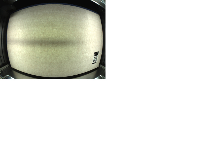
Here’s an image borrowed from Scott @ Openglow.
The lens is a very wide angle lens and the material height is used to dewarp that image. But, it can only do it for one specific height at a time, which is why the material height - or set focus - is so important.
Everything above or below that plane of material height will still experience distortion.
The set focus tool is the most accurate way to set the material height. If you use that, you won’t have to actually enter anything into the material height box; it will measure the distance from the head to the material at that point you selected, and update the camera view accordingly.
As for finding dead center, with things as accurate as they are now with the camera calibration and the set focus tool, you should be able to just mark the center of your material/cutting board - pencil dot or whatever, set focus on that spot, and then center your design based on that spot.
I go back and look at the diagnostic they posted for me of my machine when I first couldn’t get the camera calibration to work every once in a while - it just amazes me how square the image is considering what’s actually being received!
That’s another good one. I definitely need to bookmark it so I can find it the next time it comes up. 
You are correct, my 1.35" measurement is to the grid, not to the top of the tray. The top of the tray measurement is 1.49". I followed the no math measurement article I found on the community site and got the 1.35" number.
Hope you enjoyed your breakfast. Thanks again.
I see you already emailed us about this and we’re working on it there, so I’m going to close this topic.