Tutorial: Create laser joints in OnShape and exporting to the GFUI
This tutorial aims to teach you how to produce standard tab-and-slot laser jointed structures using OnShape CAD and export them to the GlowForge UI for laser cutting. This tutorial is useful even if you are an experienced OnShape user but have not done laser cutting with it. There is a more advanced CAM workflow in OnShape using the Kiri.Moto app plug-in, but we will keep it simple here.
Note: If you are an educator (elementary->college) or some other form of teacher where you can verify the school you teach through, you can get an educational account which is unlimited usage.
For this tutorial we will create a simple shelf with angle brace (that way we have to create 3-way tabs and slots). While there are a lot of steps, this is actually just super detailed, so you can see everything, in reality it’s a few clicks to actually do the “laser” part of this, but I am assuming some CAD unfamiliar users.
1. Create a new document in the Documents page (or have an existing one open).
If you do not know how to create new documents, here is the help
2. Add the necessary add-in Feature Scripts
We will need 2 FeatureScript add-ins to make our workflow function. If you are not familiar with FeatureScript, it is the geometric programming language that OnShape itself is written in, and in 2016 they opened it up to all users, so a huge number of folks have written helpful plug-ins which are shared. FeatureScript is somewhat similar to OpenSCAD’s programming language, except it produces solid geometry.
For this tutorial (and your future work) we will add 2 featurescripts: “Laser Joint” and “Auto Layout”
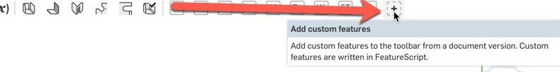
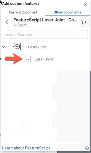
a) On the right of your document toolbar select the plus to add a featurescript
b) enter “Laser Joint” in the search
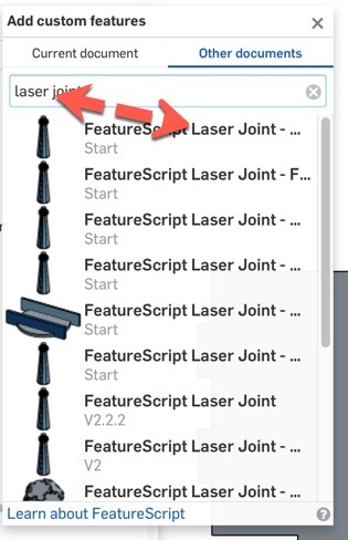
c) click on the first item in the list
d) Click on the “LJ” box. Once it is done adding it should appear as an icon on the top right
e) repeat this for the “Auto Layout” script
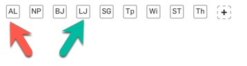
Your toolbar should now have these 2 icons (you may have more like I do, there are many, many of these).
3. Let’s create our shelves
The most important thing when designing parts for laser joints in OnShape is that the parts HAVE TO collide. This is different from most CAD design where we work super hard to make sure our parts don’t overlap in 3D space, but here the Laser Joint feature is going to subtract the slots and tabs so need to understand how we want the pieces to join up. This is different in different CAD packages.
a) set your workspace units to inches (little 3-black-lines next to the OnShape logo top left. Yeah, sorry for all metric folks, but this ultimately needs to be in inches since DXF just doesn’t work well in mm.
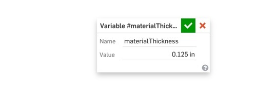
b) Let’s create a variable for material thickness. Do we need to do this, no, but wow does it make life easier. Let’s create a variable called materialThickness and set it to 0.125in (you don’t need the units, but I put it in to create design intent). Note from now on you will use #materialThickness as the variable name in usage, as the pound sign is what refers to a variable.
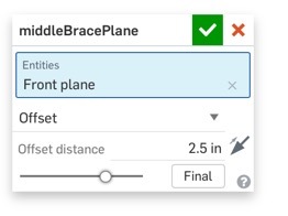
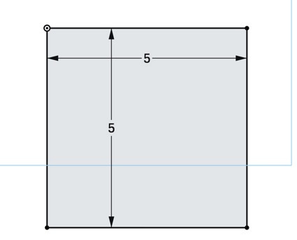
c) For this example I created an offset plane offset halfway across my shelf width of 5in. That is for this example, your design might be different, but just to make it all consistent:
d) Draw out the base shelf on the Top Plane. I made it 5x5in for this example
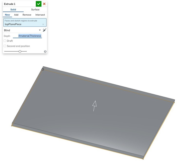
e) We extrude it by #materialThickness entered as a blind extrusion. While we are making 3D geometry remember this will ultimately become a 2D DXF file. It is critical that the pieces are all the same thickness (actually you can do tabs/slots for multiple thicknesses but let’s keep it simple)
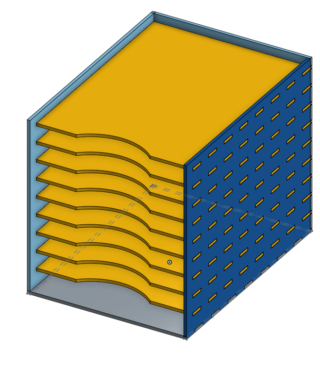
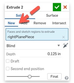
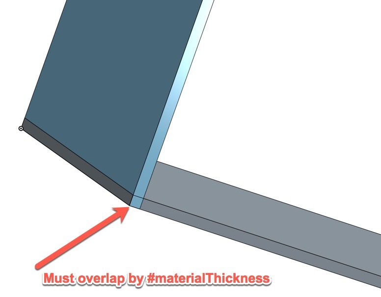
f) Now we wil sketch and extrude an intersecting part off the right plane. It is utterly critical that these parts overlap by #materialThickness or this won’t work as expected. You don’t actually have to make it the full width, but for height it must overlap by this amount. In this example we will be full width to make the final product easy.
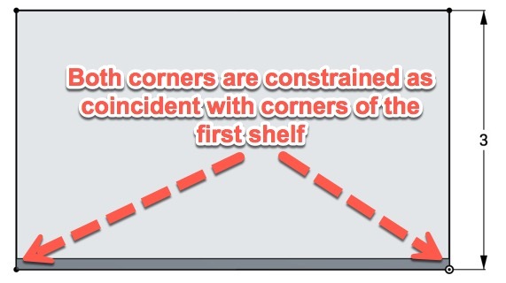
Now we extrude that as a new part (critical) as each part that you want to tab/slot must be a separate part. Note for depth I entered #materialThickness in the dialog, but once you tab or click it replaces it with the value for display.
Your end part should look like this (the overlap sort of shimmers as your rotate it)
g) Now we will create the brace just to show how fancier shapes will work (it will be a triangle). We will sketch on the mid plane we created earlier in step c.
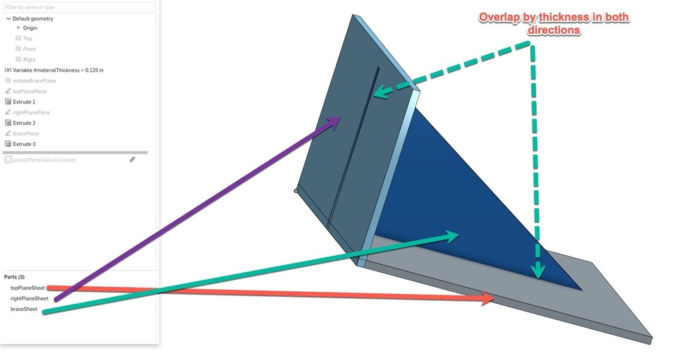
For this sketch we need to fully overlap in depth both the back and shelf part to create overlap with both existing parts. We start sketching on the mid plane (it could be on any part as long as it intersects but I like mid braces))
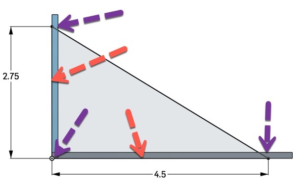
The purple arrows point vertices are constrained to the corner (origin in this case) and the 2 outer edges of our other parts. Note I deliberately made our brace shorter than the sides by making the lines with the red arrows shorter than the side length. Of course in real life you might want it to the tip or not, and you probably would use design intent by offsetting from the edge so you can change shelf size without breaking your design.
The key is that the line of your shelf (red arrow) must be on the outer lines of the other parts.
It should look like this at this point
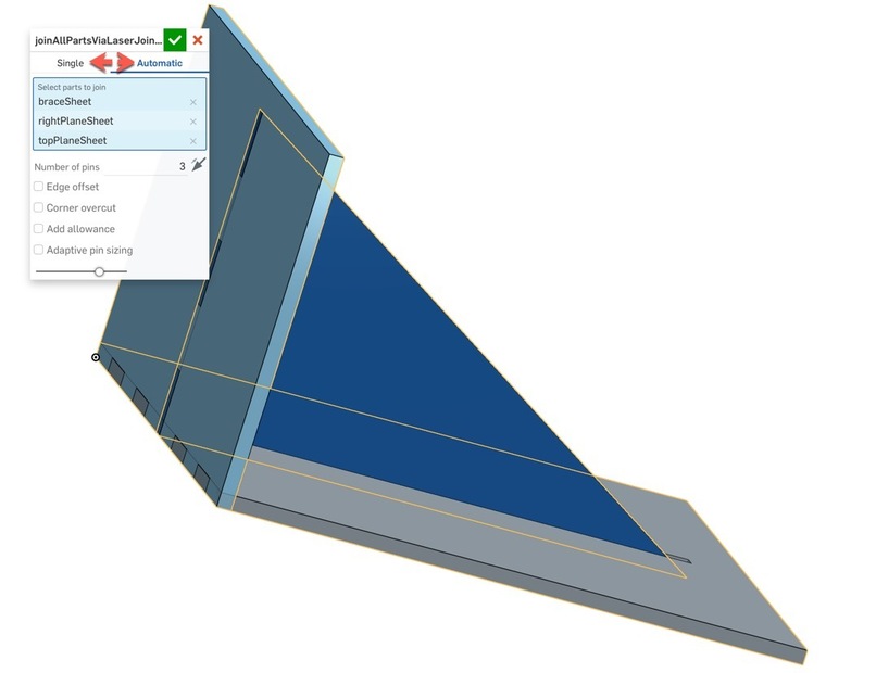
h) Now to add the laser joint feature. Click on the LJ button and you will see this dialog. You now need to make a choice, which is you want it just to take care of things for you, or you want to manage each joint manually. For this example we will do full auto (Manual is basically the same except you pick the tab part and base [slot] part for each joint). Why manual? You can change the tab count on a per joint basis.
For this example just click all 3 parts, you can set the tab count, although it may or may not do that based on geometric constraints.
And we are done creating our parts.
4. Exporting to to AI/Inkscape/etc
In a design like this where there are only a couple of parts and they are easy to access you can just export faces directly, or you can use the autolayout feature (below).
a) Simple method
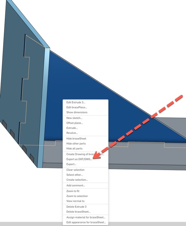
Make sure nothing is selected by clicking on the white background. Right click on any face (in this case the 2 main faces are symmetric so doesn’t matter which side) and select Export as DXF/DWG. Make sure it is set for DXF.
Repeat for each of the 3 objects. You now have 3 pieces. By the way as a hint, if you rename your part studio tab to something intelligent (like Shelf) then the DXFs will all have intelligent names (right click on the tab names at the bottom).
Open each of those files in AI/Inkscape/etc and copy/paste them into a single document. I find this works better than letting them decide how to layout on a cut sheet anyway (it never does it right). Plus this lets you add engraving, etc.
Now when I bring it into AI, before combining it, I join the paths carefully since they come from OnShape as individual lines for each side of a polygon. This isn’t “wrong” in the sense that the GFUI will correctly cut this, just not as one contiguous line which is slower. But it is super important not to just select all and path->join or it will have paths going from slot to slot.
b) Fancier method
This really is the same thing, except we can flat-pack your complex model just like an Ikea box, by having the Auto Layout script pack the parts side by side making it easier to export (this is also required prior to using Kiri.Moto - but that’s a more advanced thing)
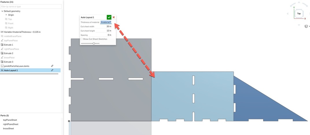
Now the Auto Layout featurescript works by taking everything of the same thickness and flat-packing them. So this is where that variable keeps everything hunky-dory. Select Auto Layout and enter the variable #materialThickness into the thickness (this way if you change from 1/8 to 1/4" plywood it will all react everywhere). Now set the cut sheet to 20x12in so it will lay out in GlowForge sized blocks.
I this case I would just right click on the parts as in the prior steps. This just makes it easier if the parts are complexly laid out. Now if you were using Kiri.Moto this was a critical step, otherwise it would slice it like a 3D object (build up layers), rather than single slice.