What is the difference between focus height and thickness?
Focus Height changes where the laser focuses whereas the thickness is the actual measured thickness of the material. The glowforge usually assumes a focus height at the top of the material being used but you can manually adjust the focus height for different effects in engraving or getting through thicker materials. It should be noted that the thickness is important for the camera to show you the proper picture in the UI.
2 Likes
Focus height means “how far above the surface of the honeycomb you want to focus the laser”.
Thickness for items on the honeycomb is generally the focus height you want, therefore, they are sort of interchangeable. There are some cases where you want to intentionally focus at a different height (called “defocusing”), like in the case of wanting a smooth engrave or perhaps a multi-pass cut on thicker materials.
Now, when you’re engraving something really thick, you have to remove the honeycomb, so now you’ve gotta do some math to get the correct focus height for your material.
Lots of info on the forums about this.
Relevant post:
Relevant search:
https://community.glowforge.com/search?q=engraving%20without%20crumb%20tray
It’s a bit of a learning curve, but spending the time to grasp all of this stuff will pay off later when you want to engrave something thick like a cutting board (or a rat skull…), etc.
Have fun. Move fast, break things, send pics ![]()
EDIT:
Since this post was written, the game has changed. Definitely look into using the set focus feature now, it can be the easiest way to get to your end goal. Lots has been written about it, just search the forum for “set focus”.
7 Likes
So if I want to engrave “more” on this piece of metal I should set focus height slightly less than the thickness?
1 Like
No, the beam is focused by the lens, so it is convergent to the point of focus, then it becomes divergent. So if you set the focus below the surface it is defocused slightly. Same if it is set above the surface, so think of the point of focus as the beam ‘waist’.
3 Likes
You can’t engrave metal, you can only mark it. It will never get any deeper. 
5 Likes
I use that no math edition of cutting without the crumb tray, and it works really well!
Stupid question…say I’m cutting a piece of 1/2" thick hardwood…and want to cut all of the way through it. Obviously, it would take multiple passes. Do I need to set it up for one pass and for the focus to be say 1/4 of the way into the board…then, run another pass with focus height 1/2 way into the board…etc? Or would I just set the focus height to basically be zero (at the bottom of my material) and let it run multiple passes in one “print”?
The correct answer is… either. Potentially. Depending on a lot of things. I think. Here’s my thinking.
If you kept one focal point, you’d probably have more consistent edges on thicker materials (not that they’d be perfect). Consistent doesn’t mean perfect, just consistent.
The beam is “in-focus” for about a tenth of an inch. However, the beam reflects back and forth on the interior of a wood or acrylic cut, making it stay in focus for longer/deeper.
Multi-pass with multiple focal points could lead to a wavering effect on the edge as the beam profile will be changing from pass to pass.
1 Like
That makes sense.
So, since we’ve established it would be better for multi-pass with one focal point, which height would that be? At zero meaning at the bottom of the material…where you want it to cut through, or still just focus on the height/surface of the material?
I’d guess somewhere in the middle to upper third.
1 Like
If you focus below the surface, the beam will be wider at the surface, which means a bigger kerf. And less penetration on the first pass because some of the beam gets intercepted. In general for cutting I focus at the surface or very near to it.
3 Likes
Focal length vs Material Thickness vs Focus Height
Without getting into the discussion of is light a ray (particle) or a wave, the light that a laser emits is coherent and the energy is emitted in a very small spectrum of the EM band. These properties let us harness the power to engrave and cut.
To aid us in these actions, there are lens in the system that will focus the energy down to a pin point. A convex lens will cause the rays to converge, where f is the focal length.
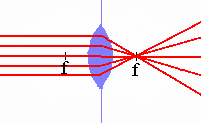
The focal length is fixed, but the Glowforge can adjust the lens system so we can focus on the top of different thicknesses of material. The maximum range of material is 1/2".
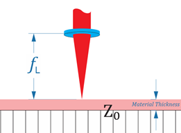
Material Thickness – when you enter a material thickness into the UI, you are telling the system that the top of my material is x” above the top of the crumb tray. The software uses the thickness to adjust lid camera focus to aid with design placement.
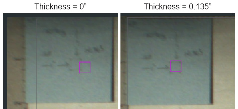
The only change in these two images is the image location adjustment as the software adjusts the image to the top of the material, based on the Material Thickness value.
Focus Height – the initial default value is the same as the material thickness, whether you select proofgrade materials or select “Use Uncertified Material” and manually enter your material thickness.
Note: If you are using proofgrade materials, the material thickness and focus height are automatically set by the system.
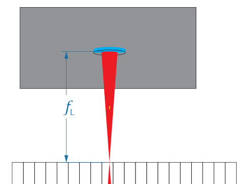
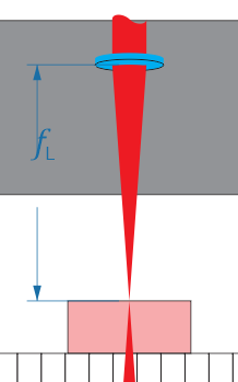
When the values are equal, the UI will adjust the lens so that the laser energy converges at the top of your material. (see image above)
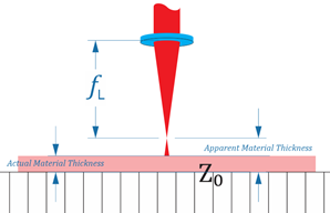
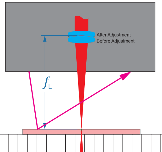
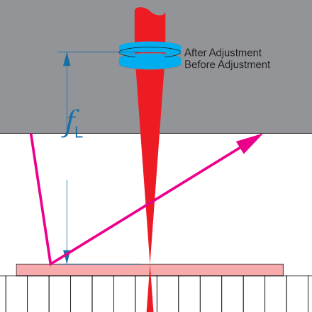
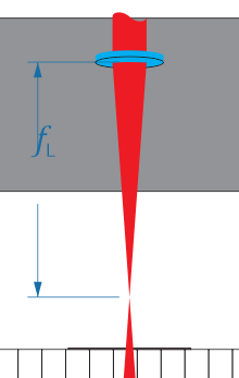
If you set the focus height greater than material height, then the convergence is above the top of the part and the laser’s energy has started to diverge. You have defocused the beam, and the energy is now spread over a larger area and as a result will not cut as sharp or deep. This will also increase the width of your kerf.
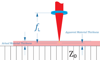
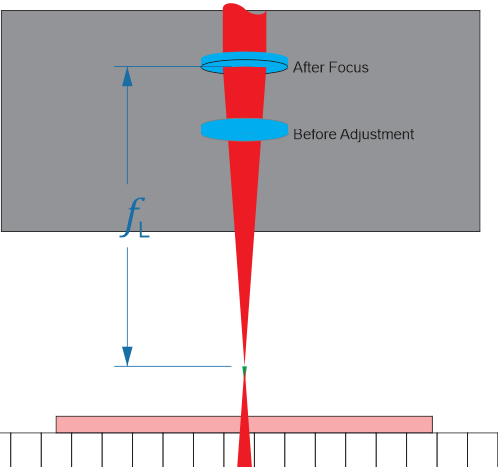
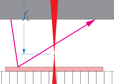
Setting the focus height less than material means that the convergence will be below the surface of the material. This will also affect the size of your kerf on the top and bottom of the material.
Note: for laser spot welding, utilizing fiber lasers, you want the focal length to be slightly below the surface to melt and fuse the material between the two parts that are being welded.
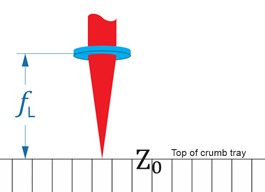
The visible Red laser beam – What does this laser do? This low power laser is used to find the actual top of the material and adjusts the lens system so that the point of convergence (focal length) is at the top of material.
If Material Thickness = Focus Height,
then the distance from the lens to the top of the material is the focal length.
If Material Thickness < Focus Height,
then the distance from the lens to the top of the material is focal length + (Focus Ht – Material Thk)
Given:
Material Thickness = 0.125
Focus Height = 0.150
Then
Ld = FL + (0.150 - 0.125)
Ld = FL + 0.025
The equation is actual the same if Material Thickness > Focus Height.
Given:
Material Thickness = 0.125
Focus Height = 0.100
Then
Ld = FL + (0.100 - 0.125)
Ld = FL + (-0.025)
Ld = FL - 0.025
Practical examples:
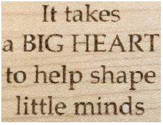
Let’s say that you select Maple Veneer as your material. The UI will initial set both the material thickness and focus height to 0.039”. However, you decided to place Medium Maple Hardwood into your Glowforge.
You’ve measured the thickness of your material and found it to be 0.125”, so you set the focus height to match. Thought was I want to utilize the Draft Engrave setting for maple veneer, but want it to work from the top of my piece of hardwood.
What you’ve actually done is set the point of convergence to 0.086” above the top of your part. Once the red laser measures the top of the material, it will adjust the lens to be focal length + 0.086” above the top of the part.
Example 2:
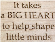
For comparison here is the same file and power settings but set for Medium Maple Hardwood.
The camera does show the true impact that can be observed visually. However, the first image is not as crisp, and less energy was applied to the material (it barely cut through the tape). The second image, in contrast, is sharp and well defined.
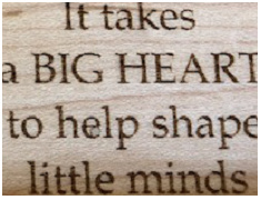
Example 3:
Let’s set the material thickness to 0.039” and focus height to 0.039? I place the same piece of medium maple hardwood into the Glowforge.
The visible Red Laser scans and finds the true top of the piece and adjusts the focal length so FL + (0.039 – 0.039), or just FL.
We get the same results as using the setting parameters for hardwood (0.125 = Matl Thk = Focus Ht)
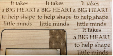
Example 4:
Let’s place another piece of material under the part, so the stack height is actually 0.250”?
I set the material height to 0.039” and focus height to 0.039”. The visible red laser scans and finds the true top of the piece and adjusts the focal length so FL + (0.039 – 0.039), or just FL.
We get the same results.
Here are all four images side by side
In conclusion.
Material Thickness adjusts the lid camera focus to aid in placing your images.
Focus Height, actually it is the difference between Focus Height and Material Thickness, sets the focal length offset from the top of the material.
The Red Laser measures the actual distance from the printer head to the top of the material and uses this value along with the focal length adjustment to set the lens distance from the top of the material.
The top of the material needs to be located between the top of the crumb tray and 1/2" above the tray. If you remove the crumb tray, then you need to place your material on risers, so the top is always within the 1/2" range (for my machine this is 1.358” and 1.858”). So long as the top is within this range, and you want the beam focus to be at the top, Material Thickness must equal Focus Height, but they can be any value between 0 and 0.500.
20 Likes
Follow up: Material Thickness does not change the physical location of the cuts.
I created a test file that consisted of 4 score lines spaced 0.125" apart. Using my Corel template, Corel Draw alignment for a repeatable setup, I positioned the lines starting location to be at
(0.312, -0.250).
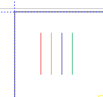
{Screenshot from Corel Draw}
Setup Parameters
The Glowforge was loaded with Medium Maple Hardwood:
Manual Score settings for all test cuts was: Speed-125, Power-11
Focus Height automatically set based on entered Material Thickness
Material Thickness varies: 0.01" (minimum allowed by the UI), 0.125", 0.250", 0.375".
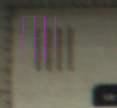
First score line - Override Material Thickness to 0.01"
Scan after the cut.
Since thickness was set to 0.01", the system translated the proposed location based on that value. However, you will notice that it actually scored the line 5/16" away from the left edge.
Focus Height and Material Height do not actually change the location of the cut, they set the focal length offset to set the laser’s convergent point relative to the actual top of the material as determined with the Red Laser scan of the material.
Second score line - Material Thickness set to 0.125"
Scan before the cut.
Notice that the artwork is now aligned with the first score. This is because the entered thickness matches the actual material height.
(It’s not perfectly aligned, but it is within the 1/4" accuracy stated by Glowforge. Especially since the image is near the top-left corner of the crumb tray, this is pretty good)
Scan after the cut
Third score line - Material Thickness set to 0.375"
(Yes, forgot and skipped 0.25”)
Scan before the cut.
Notice that the system has adjusted the image placement relative to the perceived material height of 0.375"
Scan after the cut. The third score line was cut 0.125" to the right of the second line, as defined the in the svg file.
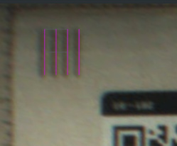
Fourth score line - (I picked up the missing thickness) Material Thickness set to 0.250"
Scan before the cut
Scan after the cut
For a final scan view, I let the Glowforge auto set material based on the QR code for Medium Maple Hardwood. Notice that all score lines are equally spaced and within the systems accuracy limits.
Actual result
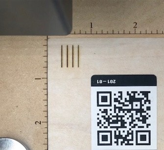
Photograph after the four test scores
Final Inspection - Measurement were checked with a 6" Starrett steel rule
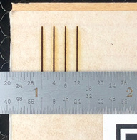
The first score line is 5/16 (0.312") from the left edge
The top of the lines was verified to be 1/4 (0.250") from the top edge.
The spacing between each line is 1/8 (0.125")
3 Likes
Are you sure the red dot measurement is used when you have set the focus height? I have the impression it is ignored.
Perhaps support can clarify this.
From the results I’ve been seeing, I would say yes.
When the system goes through the calibration cycle after you turn it on, I would say that the lens system is verified and zero’d to a known internal reference. Let’s say that zero places the beam convergence at the top of the crumb tray.
If we place an 1/8" piece of material on the tray, enter the material and focus to 0.125.
Then the focal length offset is Zero (0).
The red laser scans the material and calculates the actual height of the material.
If we were to set the material thickness and focus height to 0.500, then we would expect:
However when the red laser scans the material and finds the true top, which is actually 0.125 above the crumb tray,
and then resets the focal length placement based on the FL offset (0.500 - 0.500) or Zero,
so we end up with something like this.
Let’s try a new test:
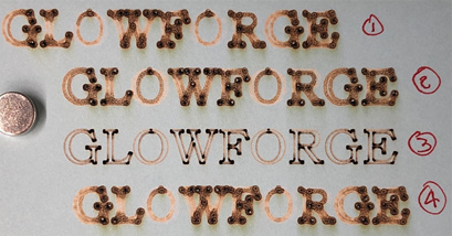
I have a file that will score the outline of the word Glowforge.
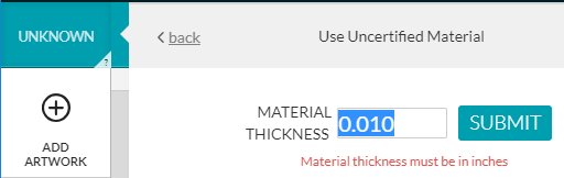
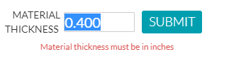
In the UI, I will tell the system that my material is 0.500" thick,
and my focus height is 0.500".
S125|P11
This would mean that I want the laser’s convergence to be on the top of the material.
So we should have something like:
Now, instead of 1/2" material, let’s place a sheet of 0.01" cardstock in the machine.
If the red laser measurement is ignored, then the beam should look like this when we run the job.
The beam would be at the systems maximum divergence, and the score width would be very broad.
Below are the results:
The top line of text settings were as defined above: Matl Thk = 0.5, Focus Ht = 0.5.
But instead of 1/2" stock, I placed a piece of card stock.
I believe the first line of text is crisp/sharp because the red laser is adjusting the setup based on the actual distance to the top of the material.
The second line of text settings were: Matl Thk = 0.01, Focus Ht = 0.5
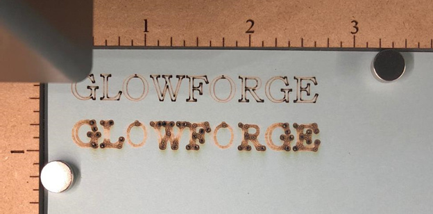
The second line is out of focus, because we told the system, the correct thickness (0.01"), set a focus height that was 0.49" above the surface. The red laser set the true top of material, and made a focal length adjustment (0.5 - 0.01) so the point of convergence was 0.49" above the part.
1 Like
The other explanation is if you set the focus height different from the material thickness it simply uses that value and ignores the red dot, In the first test they are both 0.5" so it uses the red dot value and focuses correctly. In the second case they are different so it used 0.5". Except that it can’t actually focus above 0.4"
What happens if you set the focus height to 0.417" and the material thickness to 0.4"? With your theory it would focus just below the surface of the paper. With my theory it would focus has high as possible.
1 Like
I like your ideal. So long as the difference between thickness and focus is Zero (0), then the system uses the red dot to set the top of the material. If they are different, then red dot is ignored and the system uses focus height solely to set the focal length adjustment. My earlier tests lend themselves to supporting this theory.
As a manufacturing engineer (in a machining environment) and machinist, however, if I had a system that could scan and find my material zero on every job (top of material) to setup my work coordinate system, I would utilize this information all of the time and not just on a conditional basis.
To explore further, I created another round of tests
We have two postulates:
-
The Red dot value adjusts based on actual material height, then convergence would be 0.017" above the top (.417 focus height - 0.4" material height), where actual material height is 0.010"
-
If Focus Height <> Material Thickness, then Red dot value is ignored, system uses focus height to set convergence focal length; in which case the convergence would be as high the system allows (0.417:").
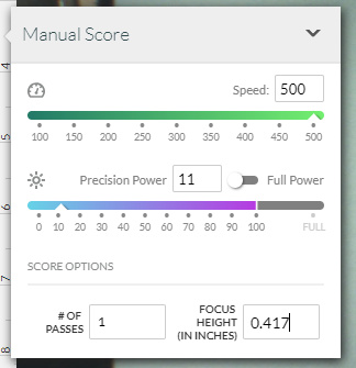
Input conditions:
Speed - 500
Power - 11
Material - 0.01" cardstock
Material Height - 0.4"
Focus Height - 0.417"
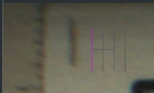
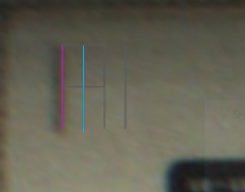
View from the UI before the score
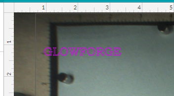
The image to be marked appears to be located off the material due to material thickness being set to 0.4"
And here is the result
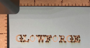
It is out of focus, but is the focal point 0.017" or 0.417" above?
While my sketches in the earlier post would appear to indicate that the angle of incidence θ is relatively large, I believe it actually somewhere around 1° 24’. We expected the results to have the cut be “out of focus” regardless of the outcome, so we need to conduct some additional tests to verify the results.
I ran three more test cut to collect and compare measurement data:
- first test, from above: Thickness - 0.4", Focus - 0.417", Speed-500, Power 11
- Thickness - 0.01", Focus 0.027", Speed-500, Power 11
- Thickness - 0.01", Focus 0.01", Speed-500, Power 11 (baseline)
- Thickness - 0.01", Focus 0.417", Speed-500, Power 11
Here are results
Measurement Apparatus
Zeiss Stemi SV-6 stereo microscope w/10X eyepiece, set to 2.0X magnification
Mitutoyo 6" Digimatic caliper
I really wish my scope was able to have a camera mounted to it for photographs. It is really neat being able to see the details of the cut, the depth of a line and the disruption in the corners and shape and degree of the burn through.
Measurement point; width of vertical line in the letter L
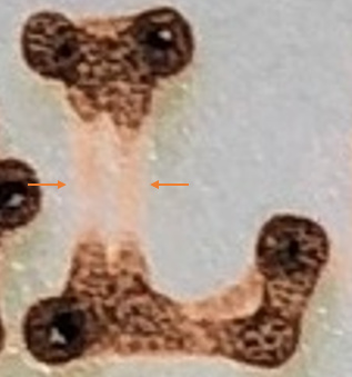
Test 1 - width ~ 0.055"
Test2 - width ~ 0.055"
Test 3 - no measurements, for visual comparison only
Test 4 - width ~0.065"
Results
Test 3 has crisp lines as expected since thickness and focus height were equal.
Tests 1 and 2 widths were the same, ~0.055". Based on inputs values, the difference between focus height and material thickness were the same; 0.017". If the system utilized the Red dot to set the actual of of material, then the results are as expected.
Test 4 is wider than both Tests 1 and 2. It is observable with the unaided eye and under strong lights. Under 20X magnification, the width of the vertical line in L is ~0.065".
Findings
Based on the results, Test cut 1 has a focus 0.017" that is above the actual surface of the part. This is confirmed with Test cut 2 where the input conditions would have placed the focal plane to be 0.017" above the top of the material.
In Test cut 4, the width of the measurement was wider than Test 1, and confirms the angle of divergence is greater in Test 4 than in Test 1. The larger angle of divergence is supported if the focal plane distance above the top of the material is 0.407".
The findings support postulate 1, the Red dot value adjusts based on actual material height and the focal plane is offset from the material top based on the difference between input material height and focus height.
This has been fun, and a great diversion from my real work. Can you think of any other conditions we could try out? Either along this avenue of exploration or is there something else you would like to try and see what happens?
What if I placed a piece of 1/2" material into the unit, and used the following setup values:
Material Thickness = 0.075", and Focus height = 0.083".
If the Red dot is ignored when Thickness <> Focus, would this mean that the convergence focal plane would be 0.417" below the surface of the material? and,
If the Red dot adjusts based on values, then the convergence focal plane would be 0.008" above the top of the surface.
Its getting late tonight (work tomorrow), but I may have to give this a try tomorrow.
4 Likes
Test 2 looks anomalous to me, are you sure you set it as stated? The difference between 0.017" and 0.027" is at most one step of the lens and I can’t see it making that much difference. The lens moves in 0.139" steps from 0 to 0.417".
Measuring the width of the L you indicated puzzles me as the L laser is scoring the outlines, so its the width of each of the two lines, not the total.
I agree treating it as a focus offset and not ignoring the red dot, would make more sense but that is not what people have said it does. Of course it would be nice if GF actually said what their machine does.
Setting the thickness and focus to a range of equal values should always be in focus if your conjecture is correct. If the red dot is ignored they should be all different.
1 Like
I’ve actually tested this by looking at the number of steps commanded to the Z-Axis in the motion files sent to the Glowforge from the cloud.
The focus is set to the laser diode measured height if the material thickness and focus height settings are the same. If those settings differ, the focus height setting takes priority.
You can download the motion files and decipher their contents on your own to verify, if you like.
7 Likes
Scott,
Thanks for the link.
I followed the steps and it downloads a .PULS file. What do I use to view the files and see the details?
thanks,