I also have the need for a 0,0 reference. I have hundreds of items that require the blank material to be set at a 0,0 stop so the engraving will be at the proper location.
@markwkruse, I hear you. will be more disciplined and try to further the conversation along. Back to work after the break now.
No rush… just trying to stay on topic.
No to the first.
I’m afraid I don’t understand the second one.
I copy pasted verbatim from my post above.
It appears from the upload of interface that marmak3261 provided that there is a scale showing the bounds of the electronic interface and cutting area inside the machine.
- is the scale shown on the interface tied to the head zero position (and consequentially to a fixed offset for the actual machine (0,0) position inside the machine… presumably (-10,5.25) from the head (0,0) based on a working area of 20x10.5 )?
- when importing the drawing file, can you “snap” the outside edges of the cut/engrave file to the 0,0 edge as shown in the interface.
This would presumably then give you precise registration of the file to a known precision location on the bed. If there is only an “optical” alignment of the drawing with lid camera or trying to look at the scales on the sides to eyeball the file alignment, there is no precision for the cut file to the part in bed.
marmak3261 was showing how the file could “hang” over the edge and show elements outside of usable area.
^^^^ What @rpegg said!
I’m sorry. I do my best. This particular thread is challenging because people have many unspoken assumptions in their questions (for example, that the laser starts at a position called 0,0 which is in the upper left corner of the bed) that are not true of the Glowforge. So the “short simple” questions are not answerable.
Also, as a note, creating a new topic in the Q&A section for a new question is always the best plan - addressing new topics in Q&A is always one of my top priorities.
@takitus, one correction: I didn’t state that any of the “margin of error in homing” examples besides getting “crumbs” stuck in the door, and said we’d add handling for that too.
No snaps in the UI, but it’s definitely in the hopper.
No. There are probably other ways to accomplish the end goal, and we have work in the hopper to extend this area of functionality. If you have any other specific operations you’d like to accomplish, sharing your plans is very helpful to us.
8 Likes
Ah, Im sorry if it was implied that those points were from the horse’s mouth, and also now that you are a horse (or robot alien haha). These were things I was just listing that came to mind that could potentially cause the camera to not be in the same place/orientation as it usually is. If you guys have that taken care of as well thats great news!
I was having flashbacks to old laptop screen hinges that had lost their rigidity causing the screen to flop around. I had to make a kickstand for a customer once hahaha
5 Likes
As im sure you know, many lasers allow you define 0,0/home to be different locations, like in each corner. Usually for the sake of being able to take advantage of that physical guide to know you are cutting where you need to be. Most people use the top left because of gantry orientation, and mirror placement, and because most lasers set that as default, but it doesnt have to be. I think the main concern is being able to align an absolute physical location on the bed to one in the software consistently and dead on accurately. But also being able to say ‘I need this whatever cut exactly 5mm from the top edge and 12mm from the left edge’.
also:
How does the glowforge homing work? Is 0,0 by default under the middle of the camera? Ive seen the head move back to the top left after a cut is finished. Is that a specific amount of mms/steps you have pre-programmed in from the center ‘home’ position?
There is no user-facing coordinate system, nor means to enter coordinates, in the UI right now.
It’s very helpful for us to understand exactly what things folks want to do so that our hopper entry for this gives maximum flexibility & ease of use. In general, our team prioritizes a bunch of projects that a bunch of people want to do that are hard/impossible under our current software quite highly, if that is indeed the case. If it’s actually easy to do what people are asking, but we haven’t explained how, that’s good to know too.
4 Likes
I think one of the points of confusion here has to do with the assumption that there is a fixed relationship between the drawing space and the bed space.
In other words that the drawing has an x,y zero point, and that once imported that point maps to some specific x,y point in the drawing interface (i.e. on the bed image), which then maps to a similar point in the physical machine.
Perhaps @dan (or @Tony) could explain how the drawing is imported (the first time) and a little bit about how the interface decides where to place it on the bed image.
Specific questions given an empty drawing with units in inches:
- If I put a 1" diameter circle centered on the 0,0 point of my drawing, where will it show up on the bed image.
- If I put a 1" diameter circle centered on the 6,6 (in inches) point of my drawing, where will it show up on the bed image.
The use case for this information is to understand how we can, for instance, engrave repeatedly on objects which have existing pre-printed text. I do understand there are ways to do this, I even described one already, but I think the thought experiment would answer the underlying question.
8 Likes
I’m actually going to defer this one to @tony because I’m phone bound right now and can’t check.
2 Likes
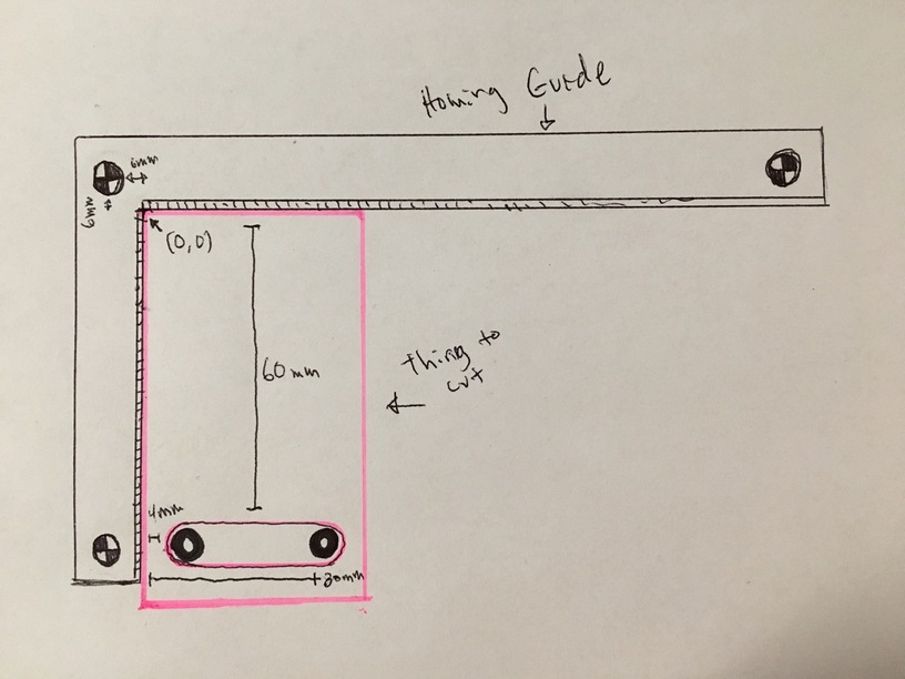
So I decided to draw up a visual guide. Something like this would be incredibly helpful. Basically its an L shaped ruler/square with 3 registration points. If the glowforge could read those points it would know exactly where it sits in the bed, and its orientation, and where the corner is that we can align objects against. Then if we can enter an offset against that corner location for our cut to be made, it would give us the desired accuracy.
For example in the drawing below I want to cut the 2 black holes in the template (pink box) ive made on my CNC machine. I know that they need to be 60mm from the top of the piece, and 4mm/30mm from the left. I know that the top corner of the material is now aligned with the homing ruler and glowforge now considers the top left inside corner of that 0,0.
I load a circle svg into the UI and tell it to move the top left corner of that svg down 60m and left 4mm from the 0,0 point glowforge has ‘generated’ based on the location of the homing ruler. then im good to go. Rinse and repeat for the next hole 30mm over.
13 Likes
This was what I was describing before. A moveable L shaped “tool” with the 3 registration points. Thanks for drawing it up so nicely. This should be mostly a software thing, but something would have to be done about how to make the precise hardware piece that the GF would recognize.
1 Like
Thanks @takitus and @julybighouse !
That is very clever and probably solves most if not all of these issues!
Given that the Glowforge can cut the template and engrave the fiducial marks we could make templates of any shape and those three points would align them repeatably.
In the mean time (i.e. until that makes it out of the hopper) I would still love to hear how the default positioning works. If it is repeatable we could have the template in the drawing and use a jig that registers against the machine (as described way above).
3 Likes
In addition to the Registration of pre-printed sheets thread, here’s another thread about how useful being able to align to registration marks would be useful…
And for ease, another link to…
1 Like
default positioning? I don’t think that would be needed. The intersection of the two arms make the initial 0,0 point, the arms would just tell the software the specific rotational orientation of the piece.
So you should be able to literally drop this piece on the tray, snug up your piece in between the arms, and go from there. If you are off by 1,2, or 85 degrees, it shouldn’t matter, the three registration points would tell the software the orientation of the piece and the software should be able to make the adjustments.
Yes, once they write the software to do that. Using the default drawing import 0,0 point is a work around until that (fairly complex) software is written/tested/deployed.
…plus there are other users with different needs that might not want the added complexity of “3-point what now?”
1 Like
I think its going to be very similar to the flip-over cut functionality they planned on having anyways… so I dont think it would be too much trouble to implement.
1 Like
It occurs to me that this whole requirement for a known origin is generally being demanded by people that have used CNC machines before.
I totally get the need for consistently placing objects and having your file consistently placed over them, but I honestly think we are selling the Glowforge team short by assuming they have irreversibly failed at delivering that, and need to implement a whole new alignment system, before the machine has even been shipped. Dan has stated repeatedly that they have gone out of their way to make sure that we will not need to interact with the Glowforge the same way we would have with other CNC machines, and that is in fact one of its biggest selling points, yet people are essentially demanding that they can use a workflow with the Glowforge that was required for those other more difficult to use CNC machines.
All the Glowforge really needs to do the same as the CNC machines that came before it is to be extremely accurate and consistent, and I’m pretty sure they’re not going out of their way to make it either inaccurate or inconsistent.
The way I see it, all that is needed to fulfill the use cases stated herein are for following two statements to be true:
- We can consistently and repeatably place our material/guides/jig in exactly the same place within the physical bed,
- Any file that we import into the user interface will be consistently placed relative to the physical bed every time that file is imported.
Item 1 it’s pretty much on us. The bed area is a physical space with some hard edges, so we should be able to figure out how to put our material or jig in the same place every time.
Item 2 is on the Glowforge team, and that requires two things:
- that the laser head itself can be consistently aligned with the physical bed (which Dan demonstrated above as being very good already and stated they are working on improvements), and
- that the software will consistently load a file in the same place relative to that bed every single time.
With this in mind it seems we have only one outstanding question; will the software consistently load the same file in the same place relative to the physical bed every time? We know the software is aware of the position of the physical bed, since we’ve seen that it can outline the non-printable area, so this seems completely doable too.
6 Likes